When Using Reed Switches in Various Sensor and Relay Applications
This resource provides detailed guidelines for safely handling Reed switches and sensors in various applications. It covers critical practices such as cutting, bending, soldering, mounting, ultrasonic use, and encapsulation. It also addresses environmental factors, mechanical shock, and electrical load management, including protection against inrush currents and contact wear, to ensure optimal performance and longevity of Reed-based components.
If there are particular areas you need help with, feel free to skip to any of the following sections:
- Cutting and Bending the Reed Switch
- Soldering and Welding the Reed Switch
- Mounting the Reed Switch on a PCB
- Using Ultrasonics
- Dropping Reed Switch Products
- Encapsulating the Reed Switch
- Temperature Effects and Mechanical Shock
- Load Switching and Contact Protection
- Capacitive and Inductive Loads
- Protection Circuitry
- Inrush Current Loads
- Reed Sensor Handling and Precautions
Cutting and Bending a Reed Switch
Many users of Reed switches for sensor and Reed relay applications try to make the sensors and or relays themselves internally. Often however, they do not observe some basic precautions and preventive measures to insure reliable operation of the switch. Below we try to cover the key areas that users and manufacturers must observe.
Reed switch modifications can be very dangerous to the Reed switch if not done properly. Primarily, this is because the reed lead is large by comparison to the glass seal. Here a balance is achieved in Reed switch sensitivity and mechanical strength. If the lead of the Reed switch was much smaller than the glass, seal stress and glass breakage would not be an issue. However, to achieve the sensitivity and power requirements in the Reed switch, a larger lead blade is necessary. With that in mind, it cannot be emphasized enough, any forming or cutting of the Reed switch leads must be done with extreme caution. Any cracking or chipping of the glass are signs that damage has occurred. Internal damage can occur with no visible signs on the seal. In these instances, seal stress has occurred, leaving a torsional, lateral, or translational stress in the seal. This produces a net force on the contact area that can affect the operate characteristics (Pull-In and Drop-Out), contact resistance, and life characteristics.
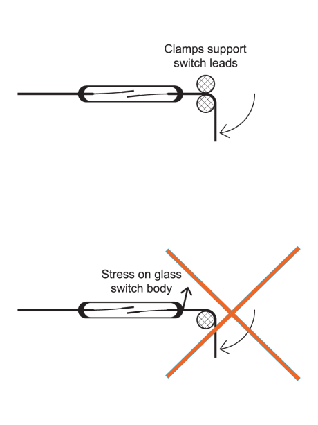
Most Reed switch suppliers can perform value added cutting and shaping of the leads in a stress-free environment using proper tooling and fixtures. Often times this is the most economical approach for users, although it may not seem so at the time.
Many times, the user will often choose to make their own modifications, and only after manufacturing and quality problems with the product, do they go back and choose the approach of letting the Reed switch manufacturer perform the value-added requirements. Figure #1 & Figure #2 illustrate the proper approach for cutting and/or bending the Reed switch. The effect on the Pull-In and Drop-Out characteristics of cutting and bending the Reed switch will be explained later in more detail.
Soldering and Welding the Reed Switch
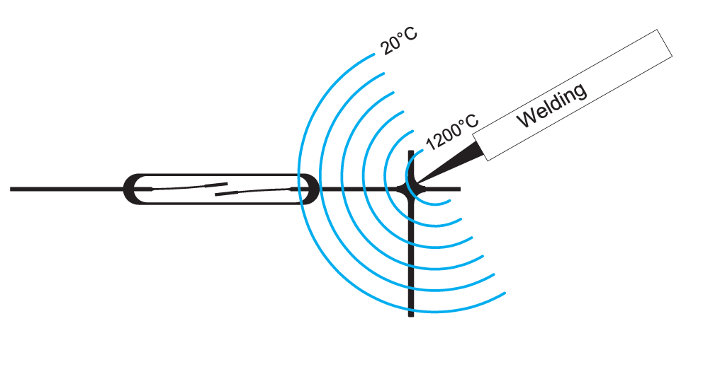
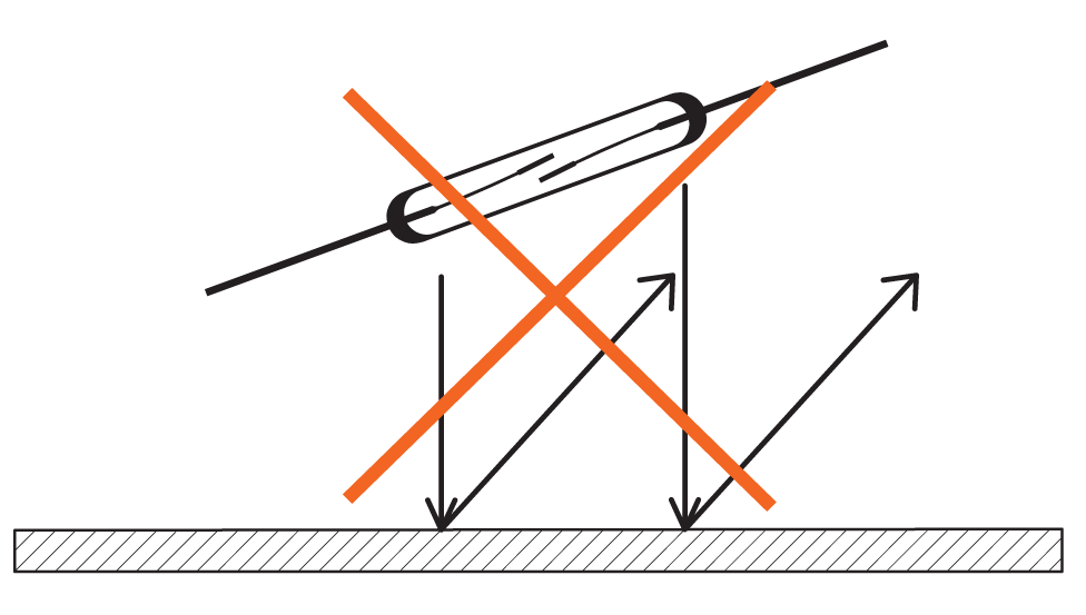
Many times, soldering or welding of the Reed switch is required. Reed switches are usually plated with a suitable solderable plating. Welding is also easily carried out on the nickel/iron leads of the Reed switch as well. However, in both processes, if not done properly, stress, cracking, chipping or breaking of the Reed switch can occur. When soldering or welding, the farther one is away from the glass seal the better. Many times, this may not be possible. Welding can be the most dangerous if one is welding very close to the seal. Here a heat front of up to 1,000 °C can conduct its way to the seal.
Since it arrives on one end of the seal first, the other end of the seal may be at 20 °C. This causes a dramatic thermal gradient to exist across the seal which can disrupt the seal in many ways, all of which, will give rise to faulty Reed switch operation. See figure #3.
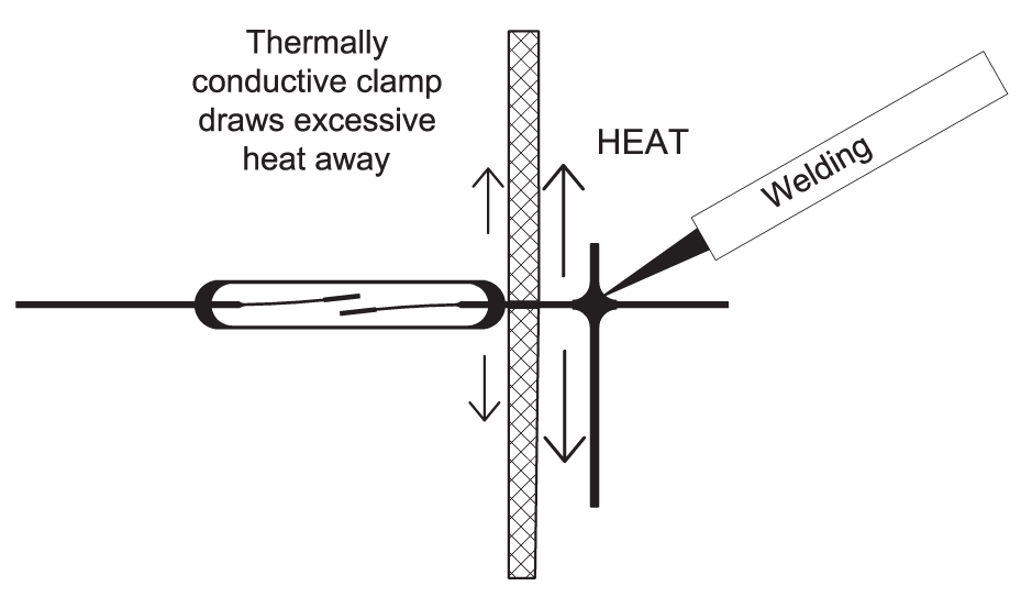
Soldering, in a similar manner, close to the seal can have the same effect to a lesser extent because of the lower solder temperatures involved (200°C to 300°C). Two ways to improve the likelihood of success are by heat sinking the lead of the Reed switch (figure #4) or by preheating the Reed switch and/or assembly. Most commercial wave soldering machines have a preheating section before the PCB or assembly is immersed into the solder wave. Here the thermal shock is reduced by the existing higher ambient temperature preexisting before the solder wave, thereby reducing the thermal gradient to the reed switch seal.
Most commercial wave soldering machines have a preheating section before the PCB or assembly is immersed into the solder wave. Here the thermal shock is reduced by the existing higher ambient temperature preexisting before the solder wave, thereby reducing the thermal gradient to the Reed switch seal.
Printed Circuit Board (PCB)
Mounting Reed products mounted on PCBs can sometimes be a problem. If the PCBs have a flex to them after wave soldering, removing this flex may be required when mounting the board to a fixed position. When the flex is removed, the hole distance, where a Reed switch for instance may be mounted, can change by a small amount. If there is no provision in the mounting to take this small movement into consideration, the Reed switch seal will end up absorbing the movement, which leads to seal stress, glass chipping or cracking. Care should be taken in this area, particularly when very thin PCBs are used and flexing or board distortion is common.
Using Ultrasonics
Another approach to making a connection to a Reed switch is ultrasonic welding. Reed switch sensors and Reed relays may also be sealed in plastic housings where the sealing process uses ultrasonic welding. In addition, cleaning stations use ultrasonic welding. In all these areas the Reed switch can be damaged by the ultrasonic frequency. Ultrasonic frequencies range from 10kHz to 250kHz, and in some cases even higher. One does not only have to be concerned with the resonant frequency of the Reed switch and its harmonics, but also of the resonant frequency of the assembly in which the Reed switch resides. Given the right frequency and the exact conditions severe damage can occur to the contacts. If using ultrasonics in any of the above conditions, be very cautious and perform exhaustive testing to insure there is no interaction or reaction with the Reed switch.
Dropping Reed Switch Products
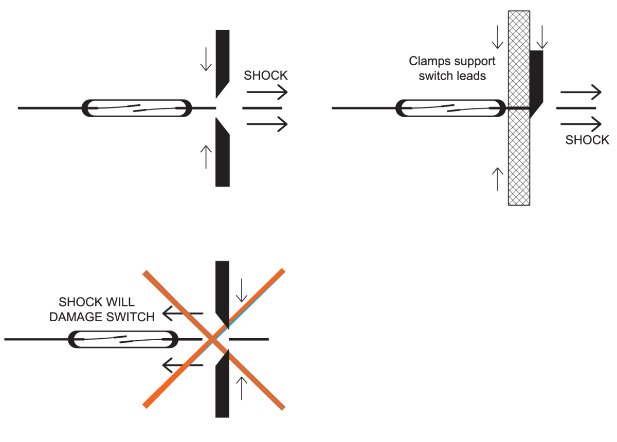
Dropping the Reed switch, a Reed sensor, or a Reed relay on a hard object, typically on the floor of a manufacturing facility, can induce a damaging shock to the Reed switch. Shocks above 200 Gs should be avoided at all costs. (See Figure #5). Dropping any of the above on a hard floor from 30 cm or more (greater than one foot) can and will often destroy a Reed switch where G forces greater than 100 G are not uncommon. Not only can the glass seal crack under these circumstances, but the Reed blades may be dramatically altered. Here the gaps may have been drastically increased, or the gaps may be closed, due to these high G forces. Simple precautions of placing rubber mats at assembly stations can eliminate these problems. Also, instructing operators that if a Reed product is dropped it cannot be used until it is re-tested.
Encapsulating Reed Switch Products
Further damage can occur to a Reed switch when one attempts to package the Reed switch by sealing, potting, or encapsulating. Whether this is done by a one or
two-part epoxy, thermoplastic encapsulation, thermoset encapsulation, or other approaches, damage to the glass seal can occur. Without any buffer, the encapsulants
crack, chip or stress the glass seal. Using a buffer compound between the Reed switch and the encapsulant that absorbs any induced stress is a good approach to eliminate this problem. Another approach would be to match the linear coefficient of thermal expansion with that of the Reed switch, thereby reducing stress as the temperature fluctuates. However, keep in mind, this approach does not take into consideration the shrinkage that occurs in most epoxies and encapsulants during the curing stage.
Sometimes a combination of both approaches may be the best way to seal a product with a Reed switch.
Temperature Effects and Mechanical Shock
Temperature cycling and temperature shock if naturally occurring in a Reed switch application must be taken into consideration. Again, temperature changes creating
movement with various materials due to their linear coefficients of thermal expansion will induce stress to the Reed switch if not properly dealt with. All our Reed sensors and Reed Relays have been designed to handle temperature changes and mechanical shock. Through rigorous qualification testing by exposure to temperature cycling, temperature shock and mechanical shock, potential design defects have been eliminated from our
products.
Load Switching and Contact Protection
The Reed switch contact rating is dependent on the switch size, gap size or ampere turn rating, contact material and atmosphere within the glass capsule. To receive the maximum life for a given load some precautions may be necessary.
Because a Reed switch is a mechanical device and has moving parts, there are circumstances where life will be shortened due primarily to contact wear. Switching no
load or loads where the voltage is less that 5 Volts @ 10 mA or less, the contacts undergo little or no wear. Here lifetimes in excess of billions of operations are expected and realized. In the 10 Volt range, higher contact wear will take place. The amount of wear is dependent upon the current switched. Generally speaking, switching 10 Volts @ 10 mA, lifetimes of 50 million to 200 million operations can be expected. If one is looking for more life under these circumstances and you cannot eliminate the actual switching of the load, mercury wetted contacts may be the correct solution. Here the contacts actually have a small amount of mercury on them so that no net metal is ever transferred from contact to contact. Life for most ‘hot’ switching loads using mercury wetted contacts will also be in the billions of operations even when switching
100’s of Volts at 10’s of mA.
Switching pure DC loads is always advised. All the data shown in our life test section, has been taken under this condition. Avoid loads with a leading or trailing power factors.
The quick disconnection creates a high induction voltage, which will result in arcing. This creates burns on the contact surface.
When the contacts see a net overall capacitive load, an inrush of current will occur when closing the contacts. Contact damage and even sticking will occur depending upon the total capacitance, voltage present and series resistance.
Tungsten filament lamps, a very popular switching load for Reed switches particularly in automotive, have inrush currents due to their cold filaments. Once the light is on the resistance in the filament rises rapidly reducing the current flow. Typically, current surges in the order of 10 to 20 times the stead state current can be expected. Knowing the cold filament resistance is important to determine the size of the inrush current. Adding some series resistance to the same circuit can have a dramatic improvement on the life of the switch.
Capacitive and Inductive Loads
Stray capacitance may be present, to some degree, when switching any voltage and current. When closing and switching a given voltage and current, the first 50 nanoSeconds are the most important (Figure #1). This is where the exact amount of arcing will occur. If there is a significant amount (depends on the amount of voltage
switched), of stray capacitance in the switching circuit, a much greater arc may occur and thereby reduce life.
When switching any sizable voltage, it is always a smart idea to place a fast current probe in the circuit to see exactly what one is switching in the first 50 nanoSeconds. Generally speaking, when switching voltages over 50 Volts, 50 picoFarads or more can be very significant to the expected lifetimes. If the Reed switch is operated remotely with a long cable connection, that cable can act like a long distributed capacitance. Shields and other potentially capacitive components can also lend their capacitance to high inrush currents.
When line voltages are present in or near sensitive circuits, be cautious. Those voltages can be coupled into the circuit creating havoc with your life requirements. Typically, a faulty Reed switch is blamed for this reduced life, when in actuality, it is a product of unforeseen conditions in the circuit.
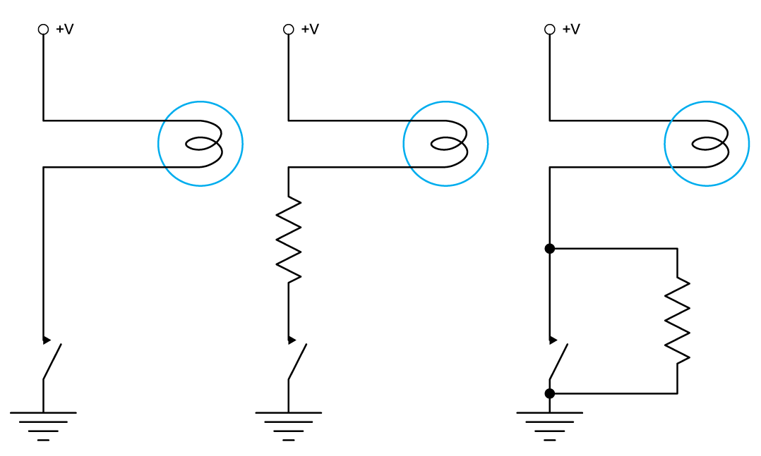
Protection Circuitry
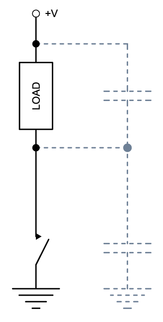
Under above conditions, protective circuitry can be added which will minimize the metal transfer at the time of the transitions but not eliminate it. Circuits shown in Figure 2 are very typical. The capacitance can be only a few pF attributed to stray capacitances or actual capacitive com-ponents in the mf range. Capacitors in an electronic circuit store charge. By their nature they like to give up their entire charge as quickly as possible. With no resistance or impedance to the flow of the current, that is exactly what will occur.
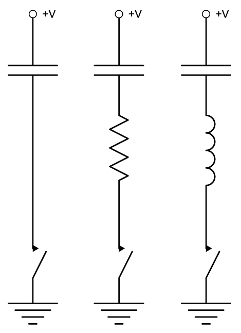
Inrush currents are to be avoided or minimized when closing the contacts of a Reed switch. If your circuit allows series resistance to be added directly in line with the Reed switch, that is generally the best choice. The higher the resistance the better as shown in Figure #3. Using an inductor or adding inductance in the circuit can be effective as well. Inductors initially impede the flow of current, thereby reducing inrush currents. Here a
careful balance must be calculated such that too much inductance is not added, thwarting its effect and creating another problem when the contacts open. Switching inductive loads such as relays, solenoids, coil driven counters, small motors or inductive circuits will all require protective circuitry to lengthen the life of the Reed contacts (see figure 8).
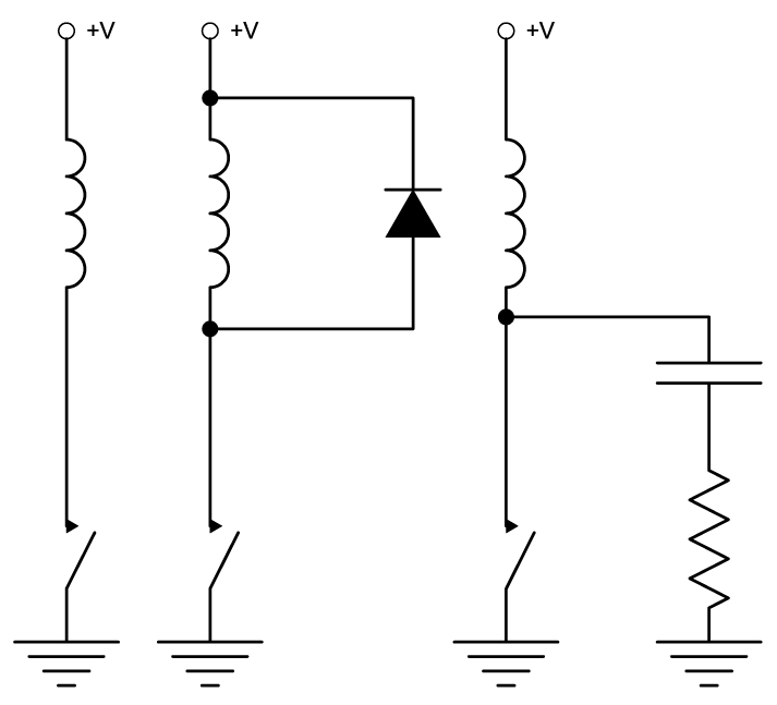
An RC network across the contact will also help.
Inrush Current Loads
Lamp loads can also produce high inrush currents when they are initially switched on. Here typically tungsten filaments are used in small bulbs which will have inrush
currents as high as 10 times their normal operating current when initially switched on. See Figure #4. Adding resistance in series with the lamp can dramatically reduce
the inrush current and play a major role in extending the life of the Reed switch.
Another approach is to add a parallel resistor across the contacts as shown in Figure #4. In this case, a small current always flows through the filament keeping it hot and its resistance high. This current flow is balanced such that the filament is not ‘glowing’.
Now when the Reed switch is activated, the current switched is close to its steady state current.
Reed Sensor Handling and Precautions
Reed sensors are composed of encapsulated reed switches. For optimal performance and longevity, please follow these handling and installation precautions:
- Usage & Temperature Considerations
- Refer to individual datasheets for recommended storage and operating temperatures.
- Ensure sensors are used within their specified environmental limits.
- Mounting Instructions
- Always mount sensors without distortion. Avoid excessive force or shock when snapping them into place.
- Prevent damage to connecting cables during installation.
- Environmental Protection
- Exposure to UV rays, saltwater, and direct sunlight can degrade sensor casings and cables.
- For outdoor or harsh environments, use sensors made from specialized, weather-resistant materials.
- Magnetic Field Interference
- Avoid mounting sensors near external magnetic fields.
- Do not install reed sensors on or with ferromagnetic materials.
- Use brass cylinder head bolts for mounting. Avoid countersunk fasteners, which may damage mounting slots or holes.
- Soldering Guidelines
- Wave soldering: Max 260°C for 5 seconds.
- Reflow soldering: Follow the solder paste manufacturer’s recommended temperature profile.
- Always consider the temperature limits of all components involved in the process.
- Shock Sensitivity
- Mechanical shocks, such as dropping the sensor, can cause immediate or delayed failure.
- Handle with care during transport and installation.