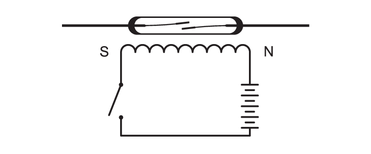
In a Reed Relay, the Reed switch uses an electromagnetic coil for activation and is shown in its simplest form in figure # 1. Reed relays require relatively little power to operate and are generally gated using transistors, TTL directly or CMOS drivers. Reed relay contacts, when switched dry, (current-less closure or less than 5 Volts @ 10 mA), will literally operate well into the billions of operations. In areas like automatic test equipment, where Reed relays may be called upon to switch tens of millions of operations per year, the Reed relay rises to the challenge.
Using the proper design, materials, placing an electrostatic shield around the Reed switch internal to the coil and driving the shield, will allow coupling or passage of
very small signals (nanoVolt signals or femptoAmpere currents) through the relay with little or no interference. See figure #2. This is virtually impossible with other
technologies except at very high cost.
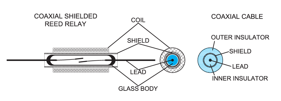
and shield (coaxial) placement.
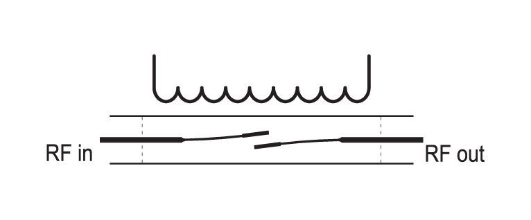
Using a coaxial shield internal to the coil, the Reed relay looks like a transmission line to high frequency signals. With Reed switches becoming smaller and smaller, overall, Reed relay packages have shrunk to less than 8 mm long, reducing the distributed capacitance (switch to shield) to less than 0.8 pF. See figure # 3 This has allowed Reed relays to carry frequencies up to 6 GigaHz without serious loss of signal strength (3 dB down). Typically, insertion losses as low as 0.2 dB and VSWR of 1.1 out to 2 GHz are now realizable. Reed Relays’ RF characteris-tics rival the gallium arsenide mosfets and at
1 GHz and above are very cost competitive. Reed relays are now commonly used in semiconductor test equipment and cellular telecommunication equipment because of
their superior better RF characteristics.
Numerous applications for Reed relays exist today and are increasing every day. Please see our applications section for more detailed Reed relay usage.