Understanding the fundamental electrical parameters of reed switch products is essential for optimizing their performance and reliability in various applications. This guide provides clear definitions and insights into key characteristics such as pull-in and drop-out points, contact resistance, switching load, and insulation resistance, equipping engineers and designers with the knowledge needed to select and apply Reed switches effectively.
If there are particular areas you need help with, feel free to skip to any of the following sections:
- Pull-In
- Drop-Out
- Hysteresis
- Contact Resistance
- Dynamic Contact Resistance
- Common Mode Voltage
- Switching Load
- Breakdown Voltage (Dielectric Strength)
- Insulation Resistance
- Dielectric Absorbtion
- Switching Voltage
- Switching Current
- Carry Current
- Stray Capacitance
- Operate Time
- Release Time
- Resonant Frequency
- Capacitance
Pull-In
Pull-In (PI) is described as that point where the contacts close. Using a magnet, it is usually measured as a distance from the Reed switch to the magnet in mm (inches) or in field strength AT, mTesla, or Gauss. In a coil, the Pull-In is measured in volts across the coil, mA flowing in the coil, or ampere-turns (AT). Generally, this parameter is specified as a maximum. No matter how well the reed blades are annealed, they will still have a
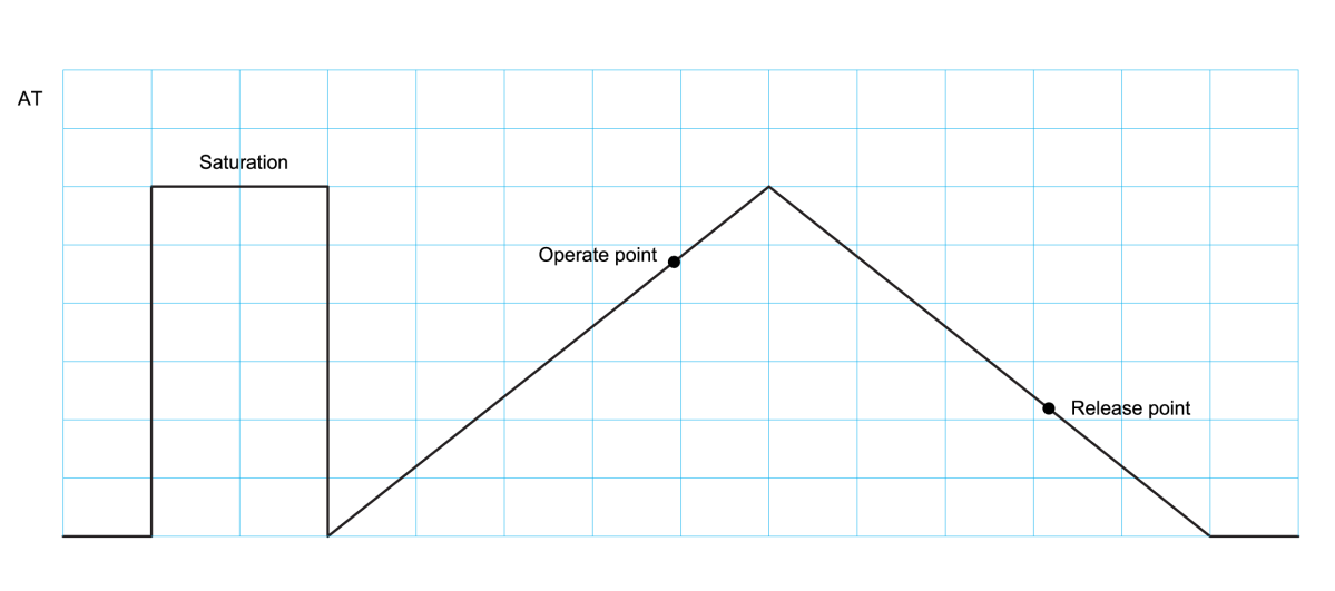
slight amount of retentivity (a slight amount of magnetism left in the blades after the magnetic field is removed or eliminated from the Reed switch). To obtain consistent
Pull-In and Drop-out results, saturating the Reed switch with a strong magnetic field first, before taking the Pull-In measurement will produce more consistent results.
See Figure #5.
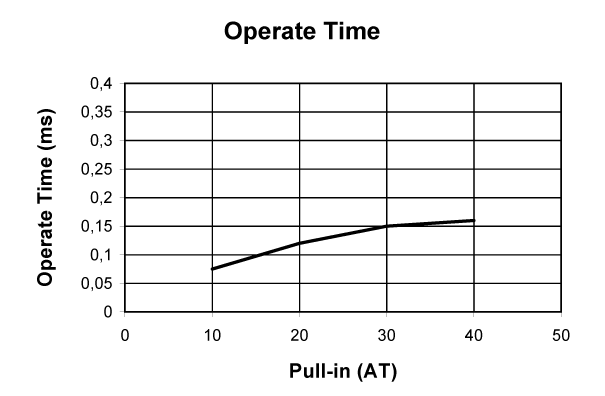
When measured in a coil, or specifically, a Reed relay, the Pull-in is subject to changes at different temperatures, and is usually specified at 20° C. See Figure #6.
Here, because the copper coil wire expands and contracts with temperature, the Pull-In or operate point will vary with temperature by 0.4% oC. Well-designed relays usually take this parametric change into consideration in the design and specification.
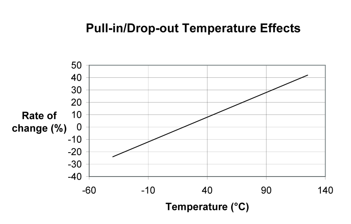
at the rate of 0.4% /°C.
Drop-Out
Drop-Out (DO) is described as that point where the contacts open and has similar characteristics as the Pull-In above. It is also described as release or reset voltage current or AT.
Hysteresis
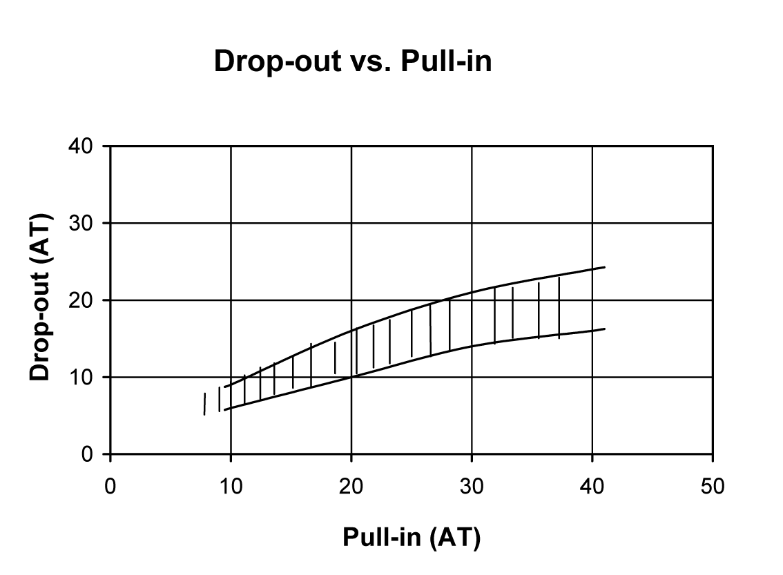
Hysteresis exists between the Pull-In and Drop-Out and is usually described in the ratio DO/PI expressed in %. The hysteresis can vary depending upon the Reed switch design, (Figure #7), where variations in plating or sputtering thickness, blade stiffness, blade overlap, blade length, gap size, seal length, etc. will all influence this parameter. See Figure 7 for example of hysteresis when using a magnet to handle a Reed switch.
Contact Resistance
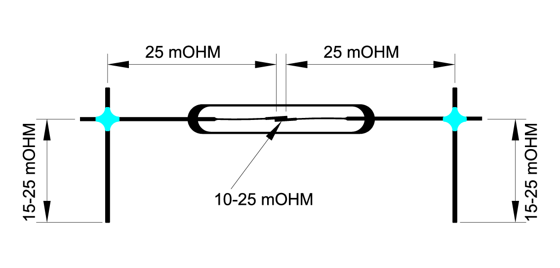
Contact Resistance is the DC resistance generated by the Reed blades (bulk resistance) and the resistance across the contact gap. Most of the contact resistance resides in the nickle/iron reed blades. Their resistivity is 7.8 x 10⁻⁸ Ohm/m and 10.0 x 10⁻⁸ Ohm/m respectively. These are relatively high when compared to the resistivity of copper, which is 1.7 x 10⁻⁸ Ohm/m. Typical contact resistance for a Reed switch is approximately 70 mOhm, 10 to 25 mOhm of which is the actual resistance across the contacts. In a Reed relay, many times the relay pins will be nickel/iron improving the overall mag-netic efficiency but adding bulk resistance to the contact resistance. This increase can be in the order of 25 mOhm to 50 mOhm. See Figure #8.
Dynamic Contact Resistance
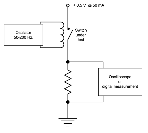
Dynamic Contact Resistance (DCR) is a true measure of the disposition of the contacts. As already described, the contact resistance is mostly made up of bulk resistance or lead resistance. Measuring the resistance across the Reed switch only gives gross indication that the contacts are functional. To give a better indication of the contacts functionality, one must look at the contacts under dynamic conditions.
Opening and closing the contacts at frequencies in the range of 50 Hz to 200 Hz can reveal much more information. Switching 0.5 Volts or less with approximately 50 mA will allow enough voltage and current to detect potential problems. This testing can be carried out using an oscilloscope or may be easily digitized for more automatic testing. One should avoid test voltages greater than 0.5 Volts to avoid ‘break-over’ (potential non-conductive films). This extremely thin film will look like an open circuit if one is switching very low signals or in current less closing of the Reed switch (closing the contacts before any voltage or current is applied across the contacts). Using a voltage above 0.5 V might hide this potential quality problem. See Figure 9.
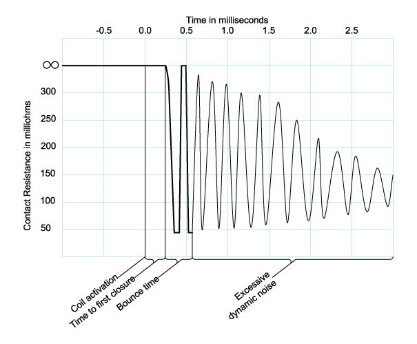
Applying the frequency described above to a coil, the contacts will operate and close in approximately ½ mA. The contacts may then bounce for about 100ms and undergo a period of dynamic noise for as much as ½ ms. This dynamic noise is generated by the contacts continuing to bounce but not opening, whereby the contact resistance varies widely where the force or pressure on the contacts varies harmonically, critically dampening in about ½ ms or less. See Figure 10. Once this dynamic noise dissipates, the contacts will then undergo a ‘‘wavering period’. Here the contacts have closed but will waver while closed for up to 1 ms or more. This wavering of the contacts in the coil’s magnetic field generates a current through the contacts. Once this effect dissipates
the contacts enter their static condition.
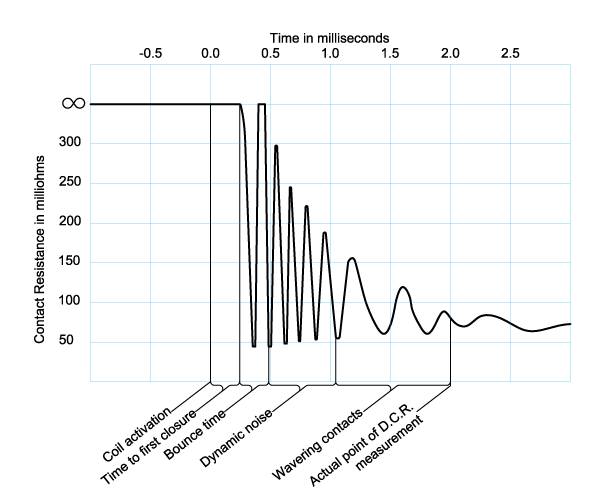
Observing the electrical pattern produced by this dynamic test can reveal much about the quality of the Reed switch. Generally speaking, once the coil voltage has been applied, the dynamic contact activity should settle down by 1 ½ ms. If the contacts continue to bounce more than 250 ms, the closing force may be weak, which may
result in a shortened life, particularly if one is switching a load of any size. See Figure #11.
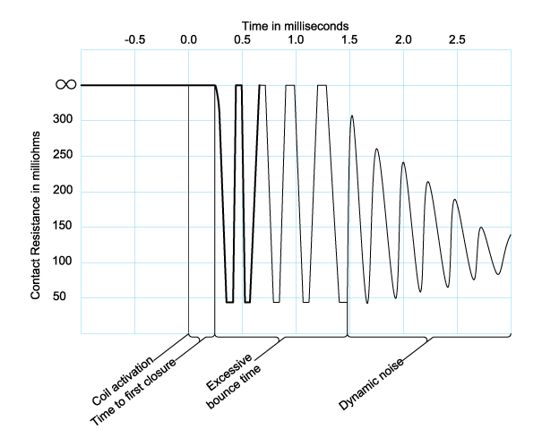
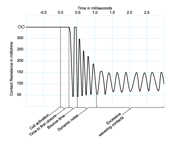
If the dynamic noise or the wavering contacts continue for periods longer than indicated, it may mean the Reed dwitch seals are weak or perhaps overstressed.
This could result in capsule cracking or breaking. Also, if the wavering produced has excessive amplitude, this could represent a condition of capsules having added
stress which could produce leaking seals. In this case, outside air and moisture may seep into the capsule producing unwanted contamination on the contacts. See Figure #12 & #13.
Also, when the contact resistance varies by a small degree with successive closures, contamination, a leaking seal, particles, loose or peeling plating may exist, potentially shortening life expectations (Figure #14). Varying the frequency applied to the coil sometimes produces more subtle awareness of resonance related problems. This will also manifest itself with higher amplitude or longer times of dynamic noise or contact wavering.
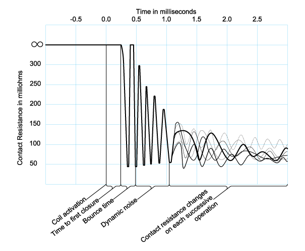
Any time long life, stable contact resistance, and fault free operation are conditions in your application, dynamically testing the contacts and having tight testing limits are a must.
Common Mode Voltage
Common Mode Voltage is also another parameter that can have a significant effect on the life of a Reed switch. Depending upon the circuit and the environment, common
mode voltages can in effect, charge stray capacitances in the switching circuit and dramatically reduce Reed switch life in an unexpected manner. Again, a fast current probe can reveal a startling voltage and current switched in that first 50 nanoSeconds, having no bearing on one’s actual load. When line voltages are present in or near sensitive circuits, be cautious. Those voltages can be coupled into the circuit creating havoc with your life requirements. Typically, a faulty Reed switch is blamed for this reduced life, when in actuality, it is a product of unforeseen conditions in the circuit.
Switching Load
Switching Load is the combined voltage and current switched at the time of closure. Sometimes there is confusion with this parameter. For a given switch, with a switching rating of 200 Volts, 0.5 Amperes and 10 Watts, any voltage or current switched, when multiplied together, cannot exceed 10 Watts. If you are switching 200 Volts, then you can only switch 50 milliAmperes. If you are switching 0.5 Amperes, then you can only switch 20 Volts.
Breakdown Voltage (Dielectric Voltage)
Breakdown Voltage (Dielectric Voltage) generally is higher than the switching voltage. On larger evacuated Reed Switches, ratings as high as 15,000 Volts DC are not uncommon. Some smaller evacuated reeds can stand off up to 4000 Volts DC. Small pressurized reed switches generally withstand 250 to 600 Volts DC.
Insulation Resistance
Insulation Resistance is the measure of isolation across the contacts and is probably one of the most unique parameters that separate Reed Switches from all other switching devices. Typically, Reed switches have insulation resistances averaging 1 x 10¹⁴ ohms. This isolation allows usage in extreme measurement conditions where leakage currents in the picoAmpere or femtoAmpere range would interfere with the measurements being taken. When testing semi-conductors, one may have several gates in parallel where the switching devices have combined leakage currents that become significant in the test measurement circuit.
Dielectric Absorption
Dielectric Absorption describes the effect different dielectrics have on very small currents. Currents below nanoAmpere are affected by the dielectric’s tendency to slow or delay these currents. Depending upon how low a current one is measuring, these delays can be on the order of several seconds. Standex Detect engineers have designed Reed relays and circuits to minimize dielectric absorption.
Switching Voltage
Switching Voltage, usually specified as a maximum in units of Volts DC or Volts peak, is the maximum allowable voltage capable of being switched across the contacts.
Switching voltages above the arcing potential can cause some metal transfer. The arc potential generally occurs over 5 Volts. Arcing is the chief cause of shorted life across the contacts. In the 5 V to 12 V range most contacts are capable of switching well into the tens of millions of operations depending on the amount of current switched.
Most pressurized Reed switches cannot switch more than 500 Volts, principally because they cannot break the arc occurring when one tries to open the contacts. Generally, switching above 500 Volts requires evacuated Reed switches, where up to 10,000 Volts is possible. Switching below 5 Volts, no arcing occurs and therefore no blade wear occurs, extending Reed Switch lifetimes well into the billions of operations. Properly designed Reed relays can switch and discern voltages as low as 10 nanoVolts.
Switching Current
Switching Current refers to that current measured in Amperes DC (peak AC), switched at the point of closure of the contacts. The higher the level of current the more sustained the arcing at opening and closing and therefore the shorter the life of the switch.
Carry Current
Carry Current, also measured in Amperes DC (peak AC), is specified as the maximum current allowed when the contacts are already closed. Since the contacts are closed, higher currents are allowed. No contact damage can occur, since the only time arcing occurs is during the opening and closing transitions. A Reed switch is also able to transport higher currents, when the pulse duration is very short, since the heating here is minimal. Conversely, unlike electromechanical armature style relays, the Reed relay can switch or carry currents as low as femptoAmperes (10-15 Amperes).
Stray Capacitance
Stray Capacitance measured in microFarads or PicoFarads is always present for example due to to conducting paths and cable. When switching voltage and current, the first 50 nanoSeconds are the most important. This is where the arcing will occur. If there is a significant amount (depending on the amount of voltage switched) of stray capacitance in the switching circuit, a much greater arc may occur, and thereby reducing life. When switching any sizable voltage, it is always a smart idea to place a fast current probe in the circuit to see exactly what one is switching in the first 50 nanoSeconds. Generally speaking, when switching voltages over 50 Volts, 50 picoFarads or more can be very significant to the expected life of the switch.
Operate Time
Operate Time is the time it takes to close the contacts and stop bouncing. Except for mercury wetted contacts, when the reed blades close, they close with enough force
to set them in harmonic motion. This critically damped motion dissipates rapidly due to the relatively strong spring force of the reed blades. One generally sees one or two bounces occurring over a 50 ms to 100 ms period. Most small Reed switches operate, including bounce, in the range of 100 ms to 500 ms. See Figure #15.
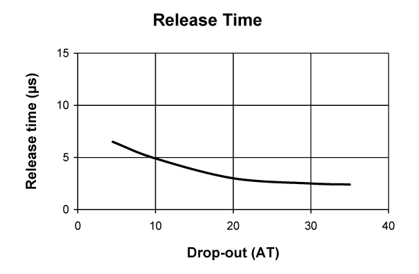
Release Time
Release Time is the time it takes for the contacts to open after the magnetic field is removed. In a relay, when the coil turns off, a large negative inductive pulse (‘kick’) occurs causing the reed blades to open very rapidly. This release time may be in the order of 20 ms to 50 ms. If a diode is placed across the coil to remove this inductive
voltage spike (which can be 100 Volts to 200 Volts), the contact opening time will slow to about 300 ms. Some designers require the fast release time but cannot have the high negative pulses potentially being coupled into sensitive digital circuity. So, they add a 12 Volt to 24 Volt zener diode in series with a diode, all of which is in parallel across the coil. Here, when the coil is turned off, the voltage is allowed to go negative by the zener voltage value, which is sufficient to cause the contacts to open generally under 100 ms. See Figure #16.
Resonant Frequency
Resonant Frequency for a Reed switch is that physical characteristic where all reed parameters may be affected at the exact resonance point of the Reed switch. Reed
capsules 20 mm long will typically resonate in the 1500 to 2000 Hz range; reed capsules on the order of 10 mm will resonate in the 7000 to 8000 range. Avoiding these specific resonance areas will insure a fault free environment for the Reed switch. Parameters typically affected are the switching voltage and the breakdown voltage. See Figure #17.
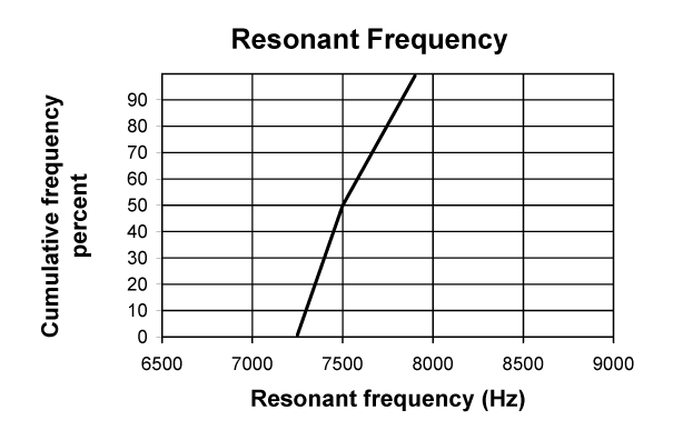
its resonant frequency distribution.
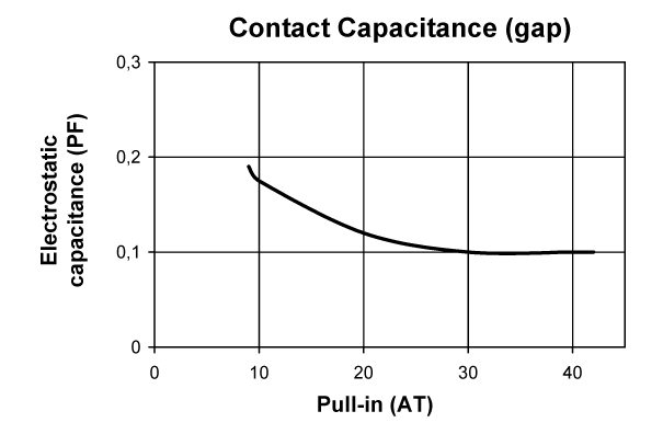
Capacitance
Capacitance across the contacts is measured in pico-Farads and ranges from 0.1 pF to 0.3 pF. This very low capacitance allows switching usage, where semiconductors
having 100’s of picoFarads, can not be considered. In semiconductor testers, this low capacitance is absolutely critical. See Figure #18.