Introduction
Using Reed switches in a sensing environment, one generally uses a magnet for actuation. It is important to understand this interaction clearly for proper sensor
functioning. Sensors may operate in a normally open, normally closed, change over or a latching mode.
In the normally open mode, when a magnet is brought toward the Reed switch the reed blades will close. When the magnet is withdrawn the reed blades will open. With the normally closed sensor, bringing a magnet to the Reed switch the reed blades will open, and withdrawing the magnet, the Reed blades will re-close. In a latching mode the Reed blades are in either an open or closed state. When a magnet is brought close to the
Reed switch, the contacts will change their state. If they were initially open, the contacts will close. Withdrawing the magnet the contacts will remain closed. When the magnet is again brought close to the Reed switch, with a changed magnetic polarity, the contacts will now open.
Withdrawing the magnet the contacts will remain open. Again, reversing the magnetic polarity, and bringing the magnet again close to the Reed switch the contacts will again close and remain closed when the magnet is withdrawn. In this manner, one has a latching sensor or a bi-stable state sensor. In the following diagrams, we will outline the guidelines one must be aware of when using a magnet. Please keep in mind the magnetic field is three-dimensional.
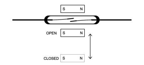
A permanent magnet is the most common source for operating the Reed switch. The methods used depend on the actual application. Some of these methods are the
following: front to back motion. See Figure #19.
Front to Back Motion
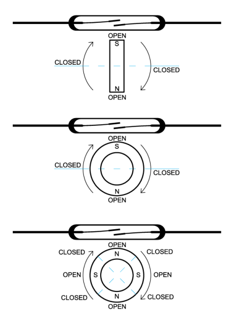
Rotary Motion
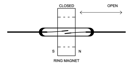
Rotary motion (see below Figure #20); ring magnet with parallel motion (see Figure #21)
Pass Through Motion
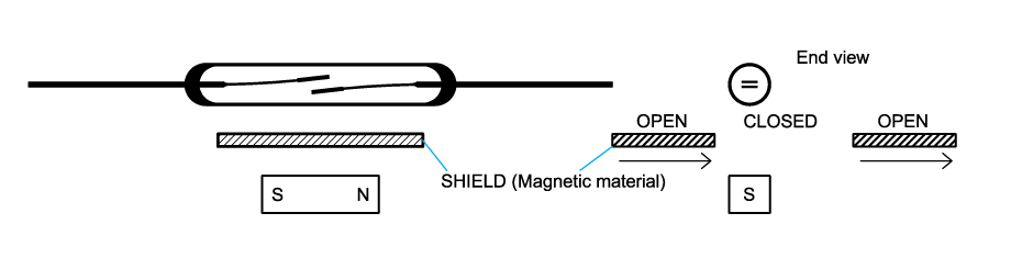
Magnetic Shield
The use of a magnetic shield to deflect the magnetic flux flow. See Figure #22.
Pivot Motion
Pivoted motion about an axis. See Figure #23.
Parallel Motion
Parallel motion (Figure #24, Figure #25, Figure #26, Figure #27, Figure #28) and combinations of the above perpendicular motion (Figure #29, Figure #30, Figure
31 and Figure #32).
Before we investigate each of these approaches, it is important to understand the fields associated with the various Reed switch vs. magnet positions and their on/off
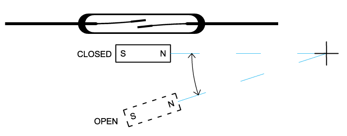
domain characteristics. The actual closure and opening points will vary considerably for different Reed switches and different sizes and strengths of magnets. First consider the case where the magnet and Reed switch are parallel. In Figure #24, the open and closure domains are shown in the x and y-axis. These domains represent the physical positioning of the magnet relative to the Reed switch along the x-axis. The closure and
opening points are relative to the movement of the magnet along this x axis, where the magnet is fixed relative to the y-axis. Here, three domains exist, wherein Reed
Switch closure can take place. Keep in mind the center domain is much stronger and the graph gives a relative idea of the closure points on a distance basis along the
y-axis. The hold areas shown, demonstrates the hysteresis of the Reed switch and will vary considerably for different Reed switches. In fluid level controls, having
a wider hold area can be beneficial, particularly if there is constant disruption to the fluid level as in a moving vehicle. Using the configuration shown in Figure #24,
the maximum distance away from the Reed switch for closure is possible. This approach has the best magnetic efficiency.
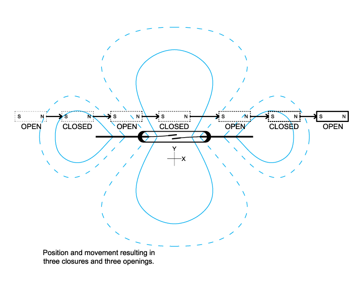
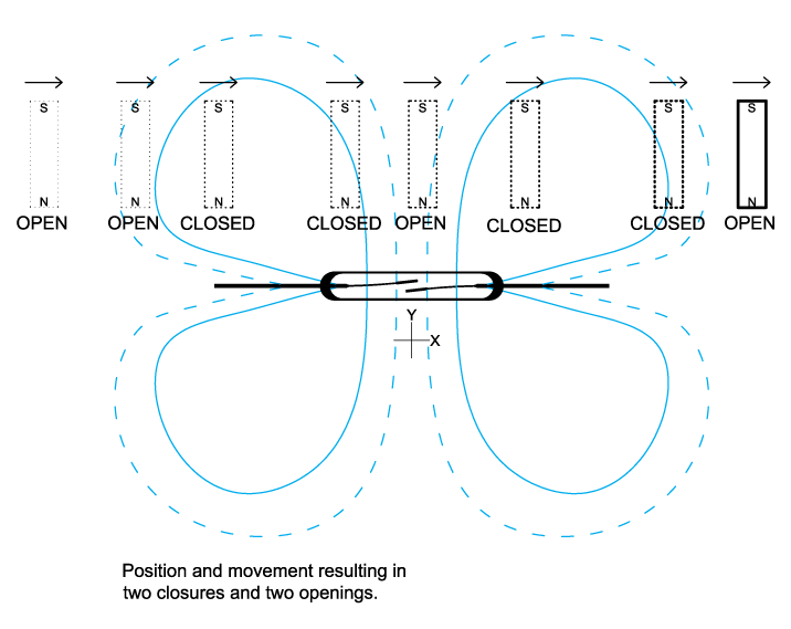
Also, for parallel motion, if the magnet and switch are close enough, parallel motion can create three closures and openings as demonstrated in Figure #25.
a Reed switch in parallel from an end point.
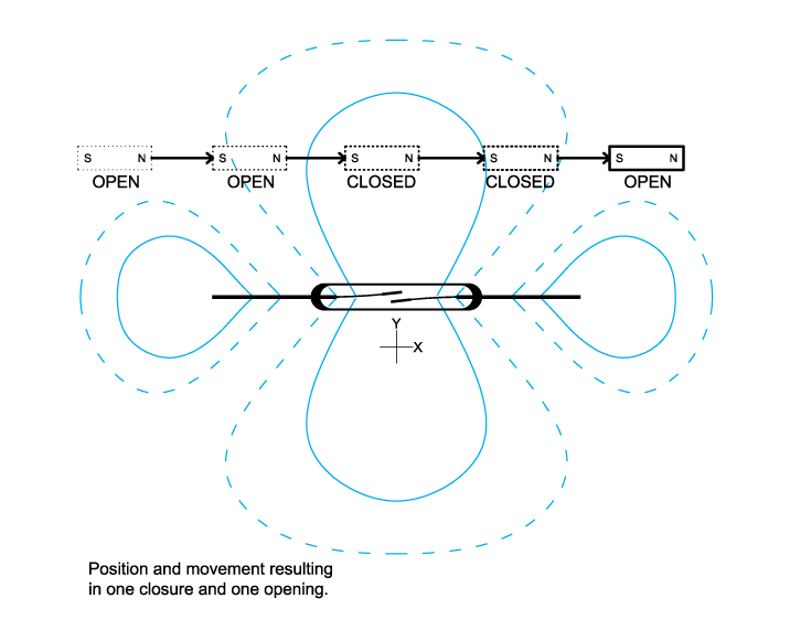
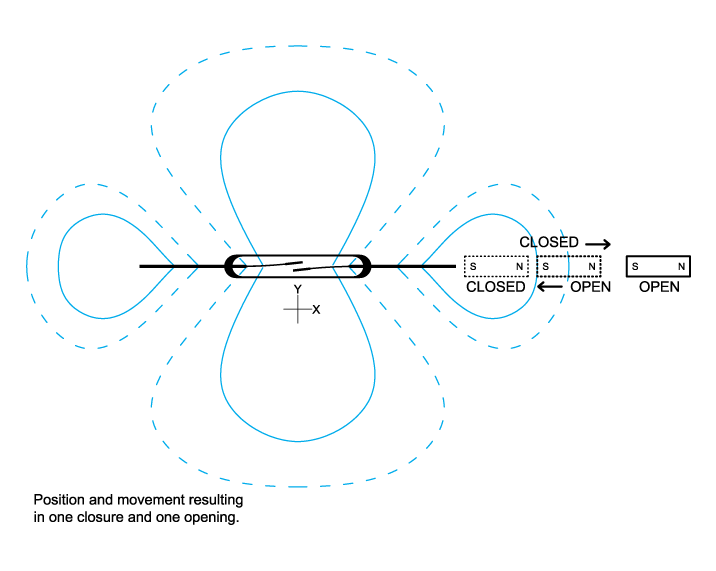
Passing the magnet by the Reed switch farther away, one closure and opening will occur. Another approach for magnets used in a parallel application with parallel motion is shown in Figure #26, where the closure point uses the smaller outer magnetic domain.
Another approach for magnets used in a parallel application, but with vertical motion, is shown in Figure #27 where the closure point uses the inner larger magnetic domain. In Figure #28 the vertical motion uses the outer magnetic domain.
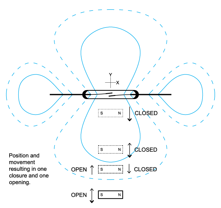
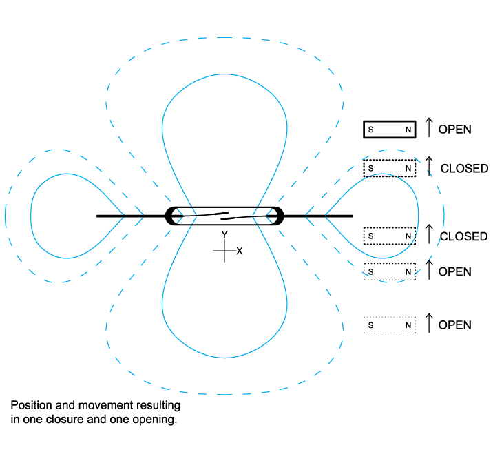
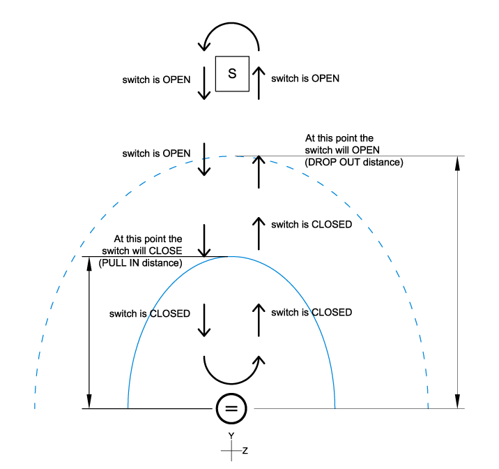
Another approach for magnets used in a parallel application, but with vertical motion, is shown in Figure #29. Please note this view is showing the y-z-axis. The closure
and opening states are clearly shown for several positions of the magnet.
In Figure #30, the magnet is perpendicular to the Reed switch. Here the x-y axis is shown with the relative closure, holding and opening points. Parallel magnet movement is along the x-axis but displaced at a distance y from the x-axis. Here two closures and openings can take place.
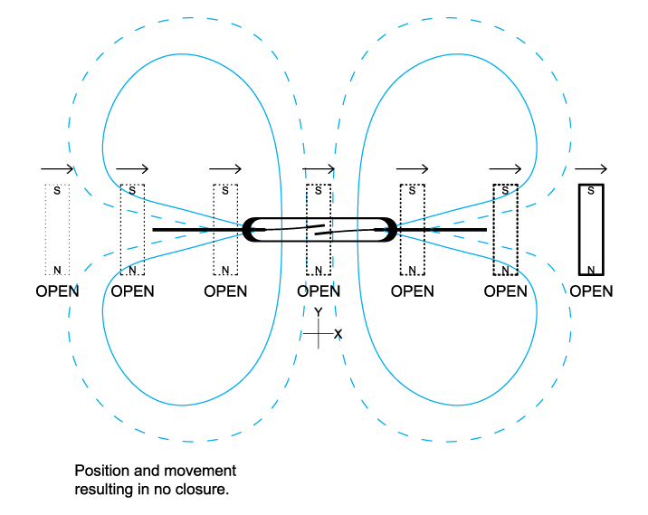
In Figure #31, the magnet is again perpendicular to the Reed switch. Magnet movement is still parallel but on and along the x-axis. No Reed switch closure takes place.
Perpendicular Motion
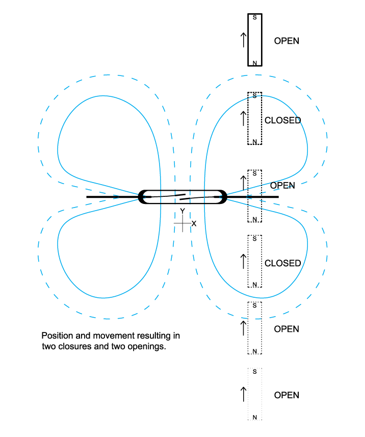
In Figure #32, the magnet is perpendicular to the Reed switch. Here the x-y axis is shown with the relative closure, holding and opening points. Magnet movement is along the y-axis but displaced a distance x from the y-axis. Here two closures and openings can take place as shown.
With the above closure and opening boundaries relative to magnet placement, an assortment of closure and open configurations can be set up when moving the magnet
in more than one axis of motion, i.e. rotary motion, etc. Also, in the above cases we held the movement of the Reed switch fixed in position.
By holding the magnet fixed and moving the Reed switch, if the application calls for it, the same expected closures and opening distances would be expected. There can be multiple poles existing in one magnet, and under these conditions the closure and opening points will change. Experimentation may be required to determine the closure and opening points.
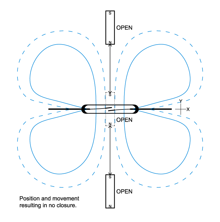
In Figure #33, the magnet is perpendicular to the Reed switch. Here the x-y axis is shown with the relative magnet movement along the actual y-axis and the magnet movement is fixed relative to the x-axis. Here no closures take place.
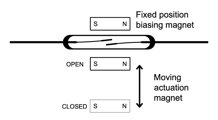
Using a Biasing Magnet
Biasing a Reed switch with another magnet will allow normally closed operation. Bringing another magnet, of opposite polarity, in close proximity to the magnet/Reed
switch assembly will open the contacts. See Figure #34.

Also, using a biasing magnet will allow Reed switch operation in the hold area or hysteresis area, thereby creating a latching sensor. (see Figure #35) In this situation,
real care needs to be taken in exact placement of the biasing magnet and the operating magnet needs to be restricted to certain areas. To switch from bi-stable state to bi-stable state the operating magnet’s polarity or direction needs to be reversed.
magnet with opposite polarity close to the Reed switch, the contacts will open and remain open when the magnet is withdrawn.
Standex Detect has developed a bridging sensor which can operate in either a normally open or normally closed state. When a sheet of ferro-magnetic material
(metal door, etc.) is brought up to the sensor the Reed switch will close; when it is withdrawn, the contacts will open (Figure #36) No external magnets are required to
operate the bridge sensor (see our MK02 Series).
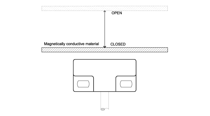
contacts will close. When the sheet is withdrawn, the contacts will open.