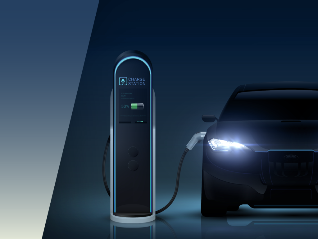
Pre-charge circuits prevent damaging inrush currents during startup in EVs and energy storage systems. Reed relays make these circuits faster, safer, and more reliable with high voltage tolerance, compact design, and long life, ideal for modern electrification.
If there are particular areas you need help with, feel free to skip to any of the following sections:
- Reed Relays Enable Pre-Charge Circuits to Energize Safely
- Reed Relays in High-Voltage Pre-Charge Circuit Applications
- How the Pre-charge Circuit Works
- Why Use Reed Relays in the Pre-Charge Circuit?
- Where You’ll Find the Pre-Charge Circuit
- Reed Relay Advantages Over Competing Technologies
- Comparison of Reed Relays, Semiconductor & Electromechanical Relays
- The Ideal Solution for Pre-charge Circuits
- Decades of High-Voltage Testing Expertise
- Ready to Optimize Your High-Voltage System?
Reed Relays Enable Pre-Charge Circuits to Energize Safely
High-voltage reed relays play a critical role in pre-charge circuits, preventing damaging inrush currents during startup in electric vehicles (EVs) and energy storage systems (ESS). These relays are ideal for EV power systems and energy storage safety applications, offering fast switching, high isolation, and long-term reliability.
The Role of Reed Relays in EV and ESS Pre-Charge Circuits
As electric vehicles (EVs) and energy storage systems (ESS) continue to grow in scale and sophistication, the demand for compact, reliable, high-voltage switching components has never been greater.
In this context, one critical area where reed relays demonstrate clear advantages is the pre-charge circuit, a vital safety and longevity feature present in all high-voltage DC systems.

Check out the full list
of Standex’s testing
and certifications:
- AEC-Q200 Qualified
- IEC 61810-4 Qualified
- IEC 60601-1 Qualified
- IEC 62109-1/2 Qualified
- IEC 60664-1 Qualified
- ISO 6469-3 Certified
- IEC 60255-27 Qualified
- UL Recognized
- RoHS, REACH Compliant
Jump to: Reed Relays Enable Pre-Charge Circuits to Energize Safely | Reed Relays in High-Voltage Pre-Charge Circuit Applications | How the Pre-charge Circuit Works | Why Use Reed Relays | Where You’ll Find the Pre-Charge Circuit | Reed Relay Advantages | Comparison of Relays | The Ideal Solution | Decades of High-Voltage Testing Expertise | Ready to Optimize Your High-Voltage System?
Reed Relays in High-Voltage Pre-Charge Circuit Applications
Reed relays are ideal for pre- charge circuits due to their high voltage handling, fast switching, and compact, rugged design. These relays are widely used in:
Pre-Charge Applications
- EVs and HEVs: Managing battery and inverter pre-charge.
- Renewable Energy: Safely connecting solar or wind systems to inverters.
- Medical Devices: Ensuring safe startup in defibrillators and imaging systems.
- Test and Measurement Equipment: For safely connecting and disconnecting high-voltage probes or circuits, protecting instrumentation.

Jump to: Reed Relays Enable Pre-Charge Circuits to Energize Safely | Reed Relays in High-Voltage Pre-Charge Circuit Applications | How the Pre-charge Circuit Works | Why Use Reed Relays | Where You’ll Find the Pre-Charge Circuit | Reed Relay Advantages | Comparison of Relays | The Ideal Solution | Decades of High-Voltage Testing Expertise | Ready to Optimize Your High-Voltage System?
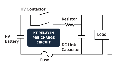
Understanding the Pre-Charge Circuit
The pre-charge circuit is used to safely charge large DC link capacitors during system startup. Without it, instantly connecting a high-voltage battery to an uncharged capacitive load would result in a massive inrush current, often exceeding the ratings of power components and causing the contactors to stick closed. The pre-charge circuit uses a resistor to limit current and allows capacitors to gradually reach the system voltage before full contactor closure.
This circuit typically consists of:
- Pre-Charge Resistor: to limit current
- Pre-Charge Relay: which temporarily connects the resistor
- A Main Contactor: to fully connect the battery once the capacitors are charged
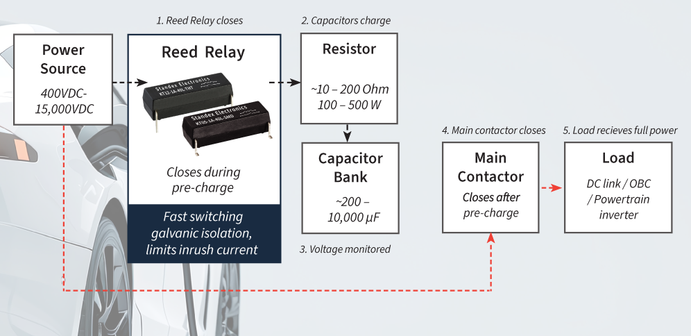
How the Pre-charge Circuit Works
Pre-Charge Circuit Design for Inrush Current Protection
1) Initial State:
Main contactor is open; capacitors are uncharged.
2) Pre-Charge Start:
Reed relay closes, routing current through a resistor.
3) Controlled Charging:
Capacitors charge gradually, avoiding inrush.
4) Voltage Threshold Reached:
System monitors until ~90% of supply voltage.
5) Main Contactor Closes
Full power is applied; relay opens. (the main contactor must close before the reed relay opens to avoid breaking current through the resistor)
This sequence protects components, extends system life, and ensures safe operation.
Jump to: Reed Relays Enable Pre-Charge Circuits to Energize Safely | Reed Relays in High-Voltage Pre-Charge Circuit Applications | How the Pre-charge Circuit Works | Why Use Reed Relays | Where You’ll Find the Pre-Charge Circuit | Reed Relay Advantages | Comparison of Relays | The Ideal Solution | Decades of High-Voltage Testing Expertise | Ready to Optimize Your High-Voltage System?
Why Use Reed Relays in the Pre-Charge Circuit?
Reed relays are particularly well-suited for the pre- charge switching function in EV and ESS systems, especially in applications switching from 400V up to 1500V DC.
They offer:
- Fast, precise switching with minimal contact bounce
- Hermetically sealed contacts for high-voltage isolation
- Compact footprint ideal for space-constrained systems
- High reliability over the lifetime
AEC-Q qualified reed relays provide low leakage, long operational life, and immunity to harsh environmental conditions, making them ideal for auxiliary control roles such as pre-charge.
Learn how to design with high-voltage reed relays
Jump to: Reed Relays Enable Pre-Charge Circuits to Energize Safely | Reed Relays in High-Voltage Pre-Charge Circuit Applications | How the Pre-charge Circuit Works | Why Use Reed Relays | Where You’ll Find the Pre-Charge Circuit | Reed Relay Advantages | Comparison of Relays | The Ideal Solution | Decades of High-Voltage Testing Expertise | Ready to Optimize Your High-Voltage System?
Where You’ll Find the Pre-Charge Circuit
Pre-charge circuits are commonly implemented in high-voltage paths feeding components such as DC link capacitors, Powertrain (HV side), On-Board Chargers (OBC), HV-LV & DC-DC converters, and ESS DC buses in Power Conversion Systems (PCS), where large capacitive loads require controlled energization to prevent damaging inrush currents. In EVs, the pre-charge circuit is typically located between the high-voltage battery pack and components like the traction inverter, onboard charger, and DC-DC converter. In ESS setups, it’s commonly placed between the battery rack and the DC bus or inverter input.
The Importance of Timing and Values
Key to the circuit’s performance is the careful selection of capacitor and resistor values. The resistor must be sized to limit the inrush current while still allowing the capacitors to charge within a defined time window, typically a few hundred milliseconds to a couple of seconds. Target voltage threshold (usually ~90–95% of full battery voltage). The charging time (Δt) depends on both the capacitance (C) and resistance (R) in the circuit. Their product defines the time constant (τ = RC), which typically results in charge times ranging
from 0.2 to 2 seconds in EVs and ESS applications. While longer charge times help reduce stress on components, they can also delay system startup. This classic charging formula is the capacitor charging equation used in RC (resistor–capacitor) circuits.
![Equation showing voltage across a capacitor in a Pre-Charge Circuit: V(t) = V_battery × [1 – exp(–t / RC)], where t is time, R is resistance, and C is capacitance. by Standex Detect](https://standexdetect.com/wp-content/uploads/sites/2/2025/12/blog-pre-charge-circuits-equation.png?w=420)
It calculates the voltage across a capacitor V(t) at a given time “t” during the charging process and helps engineers balance safety with performance. Discharge paths must also be considered during system shutdown or fault conditions, where reed relays can again play a role in safe energy dissipation from the capacitors.
By integrating high-voltage reed relays into the pre-charge circuit, system designers gain a proven solution that balances size, speed, safety, and long-term reliability, all essential in modern EV and ESS platforms.
David Stastny, Product Manager Relays
Jump to: Reed Relays Enable Pre-Charge Circuits to Energize Safely | Reed Relays in High-Voltage Pre-Charge Circuit Applications | How the Pre-charge Circuit Works | Why Use Reed Relays | Where You’ll Find the Pre-Charge Circuit | Reed Relay Advantages | Comparison of Relays | The Ideal Solution | Decades of High-Voltage Testing Expertise | Ready to Optimize Your High-Voltage System?
Reed Relay Advantages Over Competing Technologies
Reed relays particularly offer several distinct advantages over alternative switching technologies for pre-charge circuits and other high-voltage applications:
Speed:
Reed relays switch in under 1 millisecond, significantly faster than traditional electromechanical relays. This fast response supports precise control of pre-charge timing, ensuring capacitors are safely energized and reducing overall system startup delay.
Longevity and Reliability:
Reed relays offer reliability and long service life. Their hermetically sealed glass construction, filled with inert gas or vacuum, ensures the internal contacts remain protected from oxidation, moisture, and contamination. This sealing enhances both performance consistency and durability, especially in demanding environments such as EVs or energy storage systems. The internal assembly also doesn’t deteriorate with time and temperature exposure, unlike semiconductors.
No Wetting Current:
Unlike some electromechanical alternatives, reed relays do not require a minimum current (wetting current) to maintain conductivity. This is especially important if the current during the pre-charge phase is intentionally limited.
Inherent Isolation:
The hermetically sealed reed switch inside the relay inherently provides galvanic isolation between control and switched circuits as well as across the open contact. This enhances safety which is paramount in high-voltage systems to protect sensitive control electronics. Reed relays also offer a linear capacitance and a low temperature dependency.
Jump to: Reed Relays Enable Pre-Charge Circuits to Energize Safely | Reed Relays in High-Voltage Pre-Charge Circuit Applications | How the Pre-charge Circuit Works | Why Use Reed Relays | Where You’ll Find the Pre-Charge Circuit | Reed Relay Advantages | Comparison of Relays | The Ideal Solution | Decades of High-Voltage Testing Expertise | Ready to Optimize Your High-Voltage System?
Comparison of Reed Relays, Semiconductor & Electromechanical Relays
Engineers evaluating switching options for high voltage testing often compare:
| Feature | Reed Relays | Semiconductor Switches (e.g., MOSFETs, IGBTs) | Electro- mechanical Relays (EMRs) |
|---|---|---|---|
| Speed | Fast switching (<1 ms) | Extremely fast (s – s) | Slower (typically 5–15 ms) |
| Longevity | Millions + operations, load dependent | Very high (no moving parts), but may degrade with heat and voltage stress | Limited by mechanical wear (hundreds of thousands to a few million operations), load dependent |
| Wetting Current | No wetting current required | No wetting current required | Yes – requires minimum current to maintain contact conductivity |
| Isolation | High galvanic isolation, low EMI (hermetically sealed) | Moderate – opto-isolation or gate drivers needed; can generate EMI | Good isolation, but susceptible to arcing and contact bounce |
| Low Leakage | Excellent insulation resistance >10¹³ ohms | Moderate – leakage current depends on device type and temperature | Good when open, but can degrade over time due to contact contamination |
Learn how to design with high-voltage reed relays
Jump to: Reed Relays Enable Pre-Charge Circuits to Energize Safely | Reed Relays in High-Voltage Pre-Charge Circuit Applications | How the Pre-charge Circuit Works | Why Use Reed Relays | Where You’ll Find the Pre-Charge Circuit | Reed Relay Advantages | Comparison of Relays | The Ideal Solution | Decades of High-Voltage Testing Expertise | Ready to Optimize Your High-Voltage System?
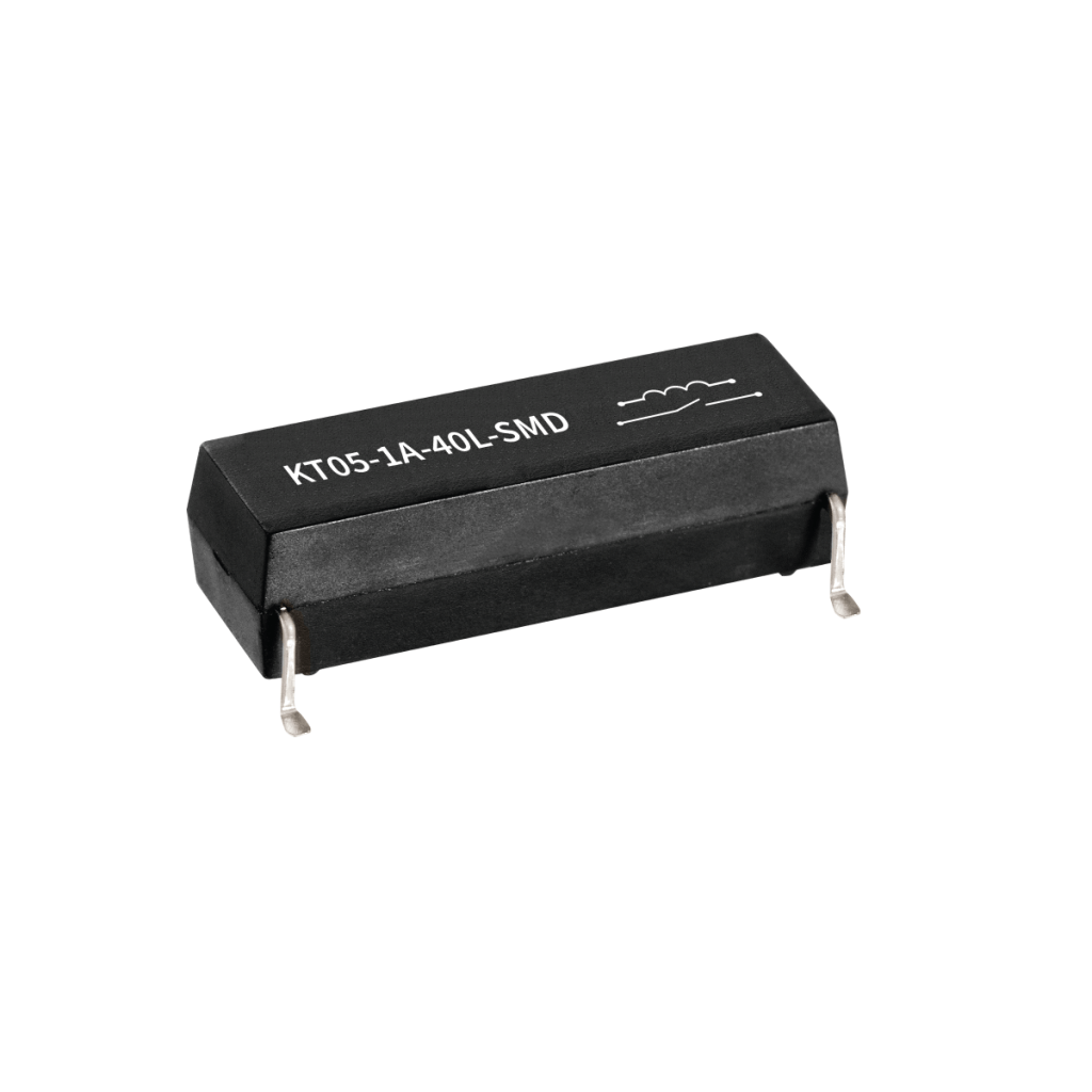
The Ideal Solution for Pre-charge Circuits
Standex Detect KT Series high-voltage reed relays are specifically designed to meet the rigorous demands of pre-charge circuits in electric vehicles, industrial systems, and other high-voltage applications. Their robust construction and performance characteristics make them a reliable and efficient choice for safely energizing sensitive systems. These hermetically sealed relays ensure inrush current protection and long-term reliability.
Key Technical Features:
- High Breakdown Voltage: With a switching voltage of up to 1.5 kV DC, breakdown voltage of 6 kV, and coil-to-contact isolation of 7 kV DC, reed relays offer a strong safety margin for high-voltage systems. They ensure reliable operation during transients while protecting control circuits and preventing interference between high- and low-voltage domains.
- Low Leakage Current: Insulation resistance exceeding 10¹³ Ohms minimizes parasitic current flow, preserving battery life and improving overall system efficiency.
- Creepage & Clearance Distances: The KT relay offers extended creepage and clearance distances in compliance with standards, such as IEC 60664-1, ensuring safe isolation in high-voltage applications, even under polluted or high-altitude conditions.
- Compact, Rugged Design: Available in both through-hole and surface mount packages with thermoset over-molding for durability. Ideal for high-density PCBs and harsh environments like automotive or industrial settings. Ideal for high-density PCBs and harsh environments like automotive or industrial settings.
Why the KT Series Reed Relays Excel
Compared to electromechanical and semiconductor alternatives, KT Series relays offer:
| Advantage | Benefit |
|---|---|
| High Voltage Tolerance | Up to 1.5 kVDC switching, 7 kVDC isolation for robust protection |
| Low Leakage | 10¹³ Ohms insulation resistance for minimal power loss |
| Compact & Durable | Sub-1 ms switching for real-time system protection |
| Fast Response | High galvanic isolation, low EMI (hermetically sealed) |
| Long Life | Millions of operations |
| Qualification & Standards | AEC-Q200 UL IEC 60810-4 IEC 60664-1 |
The Standex Detect KT Series Reed Relays deliver a powerful combination of performance, reliability, and safety for pre-charge high-voltage systems. Their superior isolation, fast switching, and long operational life make them a cornerstone for modern electrification. As industries continue to evolve toward higher voltage and more compact systems, Standex remains committed to advancing reed relay technology to meet future demands.
Jump to: Reed Relays Enable Pre-Charge Circuits to Energize Safely | Reed Relays in High-Voltage Pre-Charge Circuit Applications | How the Pre-charge Circuit Works | Why Use Reed Relays | Where You’ll Find the Pre-Charge Circuit | Reed Relay Advantages | Comparison of Relays | The Ideal Solution | Decades of High-Voltage Testing Expertise | Ready to Optimize Your High-Voltage System?
Decades of High-Voltage Testing Expertise
For over 50 years, Standex has partnered closely with customers to develop and refine relay solutions for next-generation high-voltage test systems. These collaborations result in tailored designs that meet exact specifications while maintaining cost-efficiency and reliability through minimal deviation from standard parts.
Standex Detect’s high-voltage reed relays are key enablers in advanced test and measurement platforms, where precision, durability, and safety are critical. As testing demands grow more complex, the reliability of high-voltage switching and protection systems becomes increasingly vital.
Learn how to design with high-voltage reed relays
Ready to Optimize Your High-Voltage System?
The success of our customer’s projects has driven continued innovation at Standex Detect. We are now developing advanced high-voltage reed relays to meet the growing demands of test and measurement applications. These next- generation components are designed to handle higher voltages and currents, enabling more robust and precise testing capabilities across a range of industries.
By partnering with Standex, customers gain not only a reliable solution for today’s high-voltage testing needs but also a forward-looking partner committed to advancing switching and control technologies. As your testing requirements evolve, Standex Detect will be ready with cutting-edge solutions to meet new challenges.
To learn more about how Standex Detect can support your high-voltage test and measurement projects, contact our engineering team to discuss your specific application needs.
Related Articles
-

Designing High-Density Switching Architectures Without Sacrificing Precision
Learn how engineers can increase channel density while managing capacitance, crosstalk, and PCB design constraints in modern semiconductor test systems.
-
Eliminating Downtime in Motion Systems with Precision Sensing
Learn how precision sensing helps eliminate downtime in industrial motion systems. Explore real‑world applications in automation, high‑power loads, and fluid‑dependent systems and see how reliable sensing improves uptime and system performance.
-
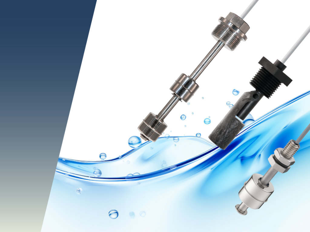
Liquid Level Sensors and Floats: An Engineering Guide to Accurate and Reliable Level Measurement
Liquid level sensors and float switches play a critical role in accurate, reliable liquid level measurement across industrial, medical, and commercial systems. This engineering guide explains how reed switch–based liquid level sensors work, compares single‑point, multi‑point, and continuous level sensing technologies, and helps engineers select the right solution for performance, compatibility, and long‑term reliability.
-
Reed Relays for High-Voltage Isolation in Electric Vehicles
Electric and hybrid vehicles operate at increasingly high voltages typically 400 to 800 VDC which raises new challenges for isolation measurement, safety, and long-term reliability. Selecting the right switching component is critical. Reed relays have emerged as a proven solution for high-voltage isolation monitoring in Battery Management Systems (BMS) and onboard chargers. This article explains…
-

Energy Efficient Sensor Solutions for AI Ready Data Centers
As AI workloads push data centers to higher power and thermal limits, energy efficiency has never been more critical. This article explores how passive, zero‑power sensor solutions help AI‑ready data centers improve cooling performance, enhance security, and maintain uptime without increasing energy consumption.