As today’s SoC devices push further into multi‑GHz RF, multi‑Gbps digital, and precision analog domains, the pressure on test systems to deliver clean, repeatable measurements has never been greater. At the heart of this performance is reliable signal switching and that’s where RF reed relays stand apart.
If there are particular areas you need help with, feel free to skip to any of the following sections:
- Reliable Signal Switching in Semiconductor Test Systems
- Switching Requirements in SoC Test Systems
- RF and High-Speed Digital Signal Considerations
- Switching Technology Options for SoC Testers
- Why Reed Relays Are Well Suited for SoC Testers
- Design Considerations for RF Reed Relays in SoC Testing
- SoC Test Architecture Example
- RF Reed Relay Solutions for SoC Test Use Cases
- Go Beyond Switching Components: Validate Your RF Signal Path
- Conclusion
- Partnering for Precision
Reliable Multi-GHz and High-Speed Digital Signal Switching in Semiconductor Test Systems
System-on-Chip (SoC) testers used in semiconductor test and measurement must route a wide variety of signals with high precision, repeatability, and speed. These systems support DC parametric measurements, functional testing, high-speed digital interfaces, and RF characterization, often within the same test sequence.
SoC testers rely on multiple tightly coupled subsystems, including pin electronics, instrumentation, calibration resources, and signal switching networks. Signal switching is implemented using relay matrices or distributed routing on load boards and probe cards. The electrical performance and reliability of these switching elements directly affect measurement accuracy, test coverage, and overall test throughput.
This application note discusses the role of RF-capable reed relays in SoC testers, outlines the key switching requirements for multi-GHz and multi-Gbps signals, compares alternative switching technologies, and explains why RF reed relays are commonly used in specific SoC tester switching layers such as instrument multiplexing, RF path selection, calibration loops, guard and isolation switching, and low-leakage measurement routing, where high isolation, low leakage, and stable signal integrity are required.

Check out the full list of Standex’s testing and certifications:
- AEC-Q200
- IEC 61810-4
- IEC 60601-1
- IEC 62109-1/2
- IEC 60664-1
- ISO 6469-3
- IEC 60255-27
- UL listed
- RoHS, REACH
Jump to: Switching Requirements | Signal Considerations | Switching Options | Why Reed Relays | Design Considerations | SoC Architecture | Signal Validation
Switching Requirements in SoC Test Systems
SoC testers must switch thousands of signals across a wide range of electrical domains. Typical requirements include:
SoC Test System Switching Requirements
- DC and low-frequency analog signals for parametric measurements
- High-speed digital signals, often operating at multi-Gbps data rates
- RF signals in the multi-GHz range for wireless and mixed-signal SoCs
- High channel density, especially on load boards and probe cards
- Long operational life, often hundreds of millions of switching cycles
Relays are used to connect and disconnect test instruments to DUT pins, isolate sensitive measurements, reconfigure signal paths between test modes, and route high-speed or RF signals without degrading signal integrity.
As data rates and frequencies increase, switching parasitics such as capacitance, inductance, and impedance discontinuities become critical. Even small variations in relay geometry or PCB transitions can introduce reflections, insertion loss, or crosstalk that negatively impact test results.
Jump to: Signal Considerations | Switching Options | Why Reed Relays | Design Considerations | SoC Architecture | Signal Validation

RF and High-Speed Digital Signal Considerations
High-speed digital signals share many characteristics with RF signals. A digital signal operating at several gigabits per second contains harmonic content well beyond its fundamental clock frequency. As a result, the switching path must support bandwidths well into the multi-GHz range to preserve rise time, edge integrity, and timing margins.
From a switching perspective, RF and high-speed digital signals have different impedance requirements. RF signal paths are typically single-ended and controlled around 50 Ω. High-speed digital interfaces are usually differential and require controlled differential impedance, tight skew control, and low mode conversion. Parallel and memory interfaces are topology-dependent and are not universally 50 Ω end-to-end.
Beyond impedance control, both RF and fast digital signal paths require:
- Low insertion loss across the intended bandwidth
- Minimal reflections caused by impedance discontinuities
- Low parasitic capacitance, particularly across open contacts
- Stable performance over temperature and lifetime
Switching components that perform well at DC or low frequencies may fail to meet these requirements once signal edge rates and frequencies increase.
Jump to: Switching Requirements | Switching Options | Why Reed Relays | Design Considerations | SoC Architecture | Signal Validation
Switching Technology Options for SoC Testers
Several switching technologies are used or evaluated in SoC test systems. Each presents advantages and tradeoffs.
Electromechanical Relays (Armature-Based)
Traditional electromechanical relays can handle high currents and voltages and are suitable for power routing or stress testing. However, their larger size, slower switching speed, and limited high-frequency performance make them less suitable for dense, high-speed SoC test architectures.
Solid-State Relays and Semiconductor Switches
Solid-state switching devices offer fast switching speeds and no mechanical wear. However, they inherently introduce on-resistance, off-state leakage, and parasitic capacitance. These characteristics reduce isolation, increase insertion loss, and can distort low-level analog or high-speed signals, limiting their usefulness in precision SoC testing.
MEMS Switches
MEMS switches can provide good RF performance and small form factors. However, challenges remain around long-term reliability, hot-switching robustness, current handling capability, and cost.
RF Reed Relays
RF reed relays combine mechanical metal-to-metal contacts with compact geometry and fast actuation. Their hermetically sealed contacts provide:
- Very low on-resistance
- Extremely high off-state insulation resistance
- Low and stable parasitic capacitance
- Excellent signal linearity
- Long operational life under signal-level loads
Modern RF reed relays are specifically engineered with controlled-impedance signal paths and internal shielding, enabling reliable operation for multi-GHz RF signals and multi-Gbps digital data.
Jump to: Switching Requirements | Signal Considerations | Why Reed Relays | Design Considerations | SoC Architecture | Signal Validation
Why RF Reed Relays Are Well Suited for SoC Testers
RF reed relays closely approximate an ideal switch for signal-level applications. When closed, the signal path is a continuous metal conductor with minimal resistance and distortion. When open, the physical air gap and low capacitance provide excellent isolation. This behavior is particularly important for RF measurements and high-speed digital validation, where leakage, nonlinearity, or parasitics can corrupt results.
Key advantages include:
- High signal integrity for both RF and fast digital signals
- Excellent isolation between channels in dense relay matrices
- Fast switching speeds, supporting high test throughput
- Very long operational life under signal-level and cold-switching conditions
- Compact packages, enabling high channel density
These characteristics make RF reed relays suitable for both entry-level SoC testers and highly complex, multi-site test platforms.
Jump to: Switching Requirements | Signal Considerations | Switching Options | Design Considerations | SoC Architecture | Signal Validation
Design Considerations for RF Reed Relays in SoC Testing
Achieving reliable RF and high-speed digital performance requires careful relay design.
Relay Design Considerations
Signal Path Geometry
The characteristic impedance must remain consistent from PCB entry, through the relay, and back to the PCB. Changes in geometry or dielectric environment can cause reflections and insertion loss.
Package Materials
Ceramic substrates and thermally stable mold compounds help maintain dimensional stability and consistent electrical performance over temperature.
Shielding
Internal electrostatic shielding reduces capacitive coupling and improves isolation at higher frequencies. Magnetic shielding prevents interaction between coils in dense layouts.
Lead Configuration
Surface-mount lead styles are optimized to minimize parasitics and integrate with controlled-impedance PCB layouts.
Jump to: Switching Requirements | Signal Considerations | Switching Options | Why Reed Relays | SoC Architecture | Signal Validation
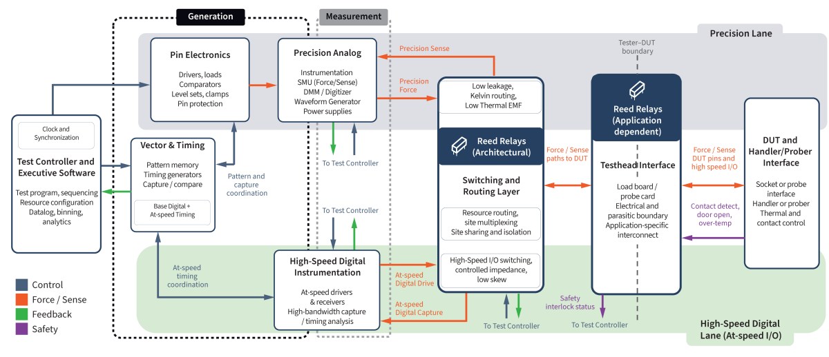
SoC Test Architecture Example
Click the test diagram to view in a larger format.
Jump to: Switching Requirements | Signal Considerations | Switching Options | Why Reed Relays | Design Considerations | Signal Validation
RF Reed Relay Solutions for SoC Test Use Cases
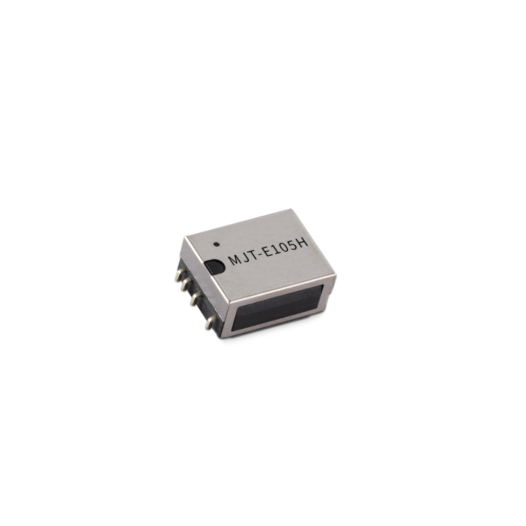
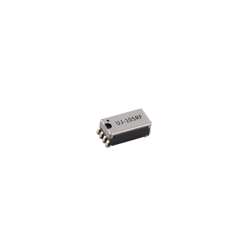
Standex / Sanyu offers a portfolio of RF reed relays designed to address the full range of SoC test requirements, from compact high-frequency switching to dense matrix architectures.
Signal-level switching performance supports -3 dB bandwidths up to 8 GHz, depending on package style and geometry. Selected series are capable of supporting high-speed digital data transfer with stable eye behavior for high-speed digital data rates up to the ~6 to ~9 Gb/s range under defined test conditions.
This performance is enabled by very low open-contact capacitance (~0.2–0.5 pF), stable contact resistance in the tens of milliohms, and compact electrical length with controlled signal geometry.
When implemented with appropriate PCB interconnect design, these reed relays provide a reliable solution for multi-GHz RF path selection and multi-Gb/s digital switching in complex SoC test systems.
| Relay Series | Typical SoC Test Use Case |
|---|---|
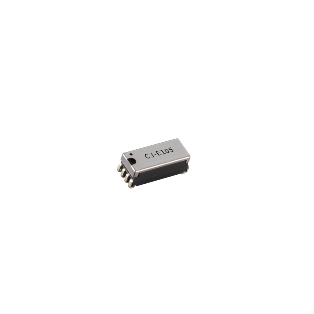
| CRF Series | Multi-GHz RF signal routing, high-speed digital channels requiring lowest insertion loss |
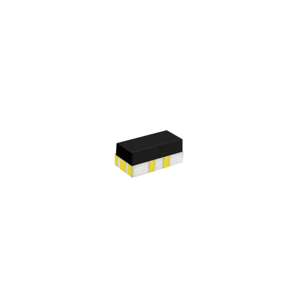
| U Series | Ultra-compact load boards, multi-GHz RF and high-Gbps digital switching where space is critical |
| C Series | High-density surface-mount relay matrices for mixed RF, digital, and analog SoC testing |
| M Series | General-purpose SoC pin electronics, functional test paths, and mixed-signal routing. Available as Normally Open contact in 1A and 2A Form |
| MT Series | Differential signal switching for high-speed serial interfaces. Available in a Changeover Form 1C and 2C |
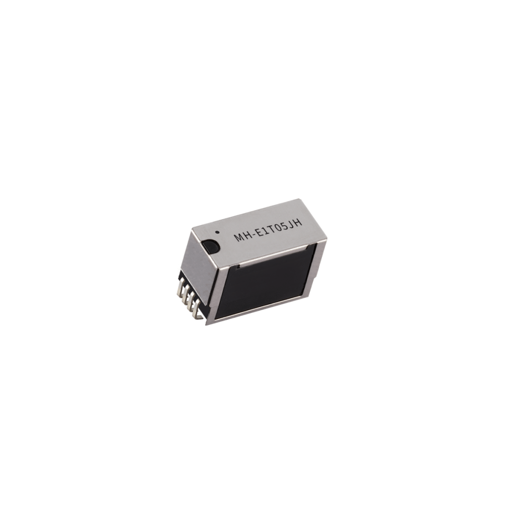
| MH Series | Very high channel-count relay matrices and dense ICT/FCT style SoC test systems. Extra small relay, available in a Changeover Form 1C |
Across these series, emphasis is placed on controlled impedance, low insertion loss, high isolation, long life, and consistent performance in high-density layouts.

Jump to: Switching Requirements | Signal Considerations | Switching Options | Why Reed Relays | Design Considerations | SoC Architecture | Signal Validation
Go Beyond RF Switching Components: Validate Your RF Signal Path
Selecting the right RF relay is only part of the challenge, validating real-world performance is where true system confidence is built.
Standex Detect goes beyond switching components by providing RF evaluation boards designed to accelerate your development process. When operating at multi GHz frequencies, even small discrepancies between modeled and real-world behavior can impact yield and performance.
Our RF demo boards enable engineers to:
- Characterize insertion loss, isolation, and return loss with precision
- Optimize PCB layout and signal routing strategies
- Feed accurate data into simulation and modeling tools
- Accelerate time-to-validation for semiconductor test systems
The result?
Faster design cycles and greater confidence in your final system performance.
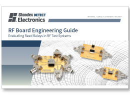
RF Demo Board Engineering Guide:
The most successful RF test designs don’t rely on assumptions. They rely on measured data aligned with real-world conditions and that’s exactly what our evaluation boards deliver.
Download the Engineering Guide
Jump to: Switching Requirements | Signal Considerations | Switching Options | Why Reed Relays | Design Considerations | SoC Architecture | Signal Validation
Conclusion
As SoC devices continue to integrate RF, high-speed digital, and precision analog functions, the demands placed on test system switching components continue to increase. While alternative switching technologies exist, RF reed relays remain a proven and widely adopted solution due to their unique combination of signal integrity, reliability, switching speed, and density.
By understanding the electrical and mechanical challenges of SoC testing and designing relays around these constraints, Standex / Sanyu provides RF reed relay solutions that enable accurate, repeatable, and high-throughput semiconductor testing across a broad range of applications.

Partnering for Precision
For When it Matters – The Right Design, at the Right Time, at the Optimal Cost.
Designing with RF reed relays for SoC test systems is not just about selecting components, it’s about ensuring signal integrity, repeatability, and measurement accuracy at high frequencies and fast switching speeds. From controlling impedance and minimizing insertion loss to reducing crosstalk and maintaining isolation in dense ATE architectures, every design decision directly impacts test performance and yield.
That’s why leading engineers partner with Standex Detect, not simply as a component supplier, but as a fully integrated engineering and manufacturing partner for precision RF switching solutions.
End-to-End Design
With complete control from reed switch fabrication to finished RF relay assembly, Standex Detect designs, manufactures, tests, and qualifies solutions entirely in-house. This vertical integration ensures tight tolerance control, consistent RF performance, and faster development cycles, critical for applications requiring high-frequency signal routing, low insertion loss, and reliable switching over millions of cycles.
Custom Engineered
Our approach goes beyond standard products. While many RF designs begin with a catalog relay, more than 35,000 customer programs have evolved into custom-engineered reed relay solutions tailored to exact electrical, mechanical, and signal performance requirements.
Whether optimizing impedance matching for GHz-frequency signals, refining shielding to minimize EMI and crosstalk, or tuning contact geometry for consistent RF performance over life, every parameter is engineered to fit the application, not the other way around.
Global Manufacturing
Equally important is global scale. With engineering and manufacturing operations across North America, Europe, and Asia, Standex Detect provides the flexibility and supply chain resilience required for high-volume semiconductor test programs, from early validation through full production deployment.
Application Leadership
This capability is grounded in deep technical leadership. As the world’s largest manufacturer of reed switches (>700 million annually), Standex Detect combines materials science, RF design knowledge, and proprietary life-cycle testing to ensure stable, repeatable performance in demanding environments such as semiconductor ATE, SoC and wafer-level testing, telecom infrastructure, and high-speed instrumentation.
Co-Engineering Partnership
Most importantly, collaboration begins early. Standex Detect works directly with your engineering team, from concept and simulation through validation and production, to optimize RF switching performance, reduce signal degradation, and accelerate time to market in complex test systems.
The result is more than a relay, it’s a precisely engineered RF switching solution designed to meet your application’s frequency, signal integrity, and lifecycle requirements.
When precision, reliability, and lifecycle performance matter most, Standex Detect delivers engineered RF relay solutions, not just components.
Engineer Your Next
RF Test Design
When signal integrity, switching speed, and measurement accuracy matter, the right partner makes the difference.
Standex Detect works alongside your team to design, validate, and deliver RF switching solutions optimized for your exact application, not forced into standard constraints.
What You Gain:
- Custom-engineered RF relay solutions tailored to your frequency and signal requirements
- Support from concept through validation and production
- Proven performance in high-speed semiconductor and ATE environments
- Global manufacturing with supply chain stability
Related Articles
-

Designing High-Density Switching Architectures Without Sacrificing Precision
Learn how engineers can increase channel density while managing capacitance, crosstalk, and PCB design constraints in modern semiconductor test systems.
-
Eliminating Downtime in Motion Systems with Precision Sensing
Learn how precision sensing helps eliminate downtime in industrial motion systems. Explore real‑world applications in automation, high‑power loads, and fluid‑dependent systems and see how reliable sensing improves uptime and system performance.
-
Liquid Level Sensors and Floats: An Engineering Guide to Accurate and Reliable Level Measurement
Liquid level sensors and float switches play a critical role in accurate, reliable liquid level measurement across industrial, medical, and commercial systems. This engineering guide explains how reed switch–based liquid level sensors work, compares single‑point, multi‑point, and continuous level sensing technologies, and helps engineers select the right solution for performance, compatibility, and long‑term reliability.
-

Reed Relays for High-Voltage Isolation in Electric Vehicles
Electric and hybrid vehicles operate at increasingly high voltages typically 400 to 800 VDC which raises new challenges for isolation measurement, safety, and long-term reliability. Selecting the right switching component is critical. Reed relays have emerged as a proven solution for high-voltage isolation monitoring in Battery Management Systems (BMS) and onboard chargers. This article explains…
-

Energy Efficient Sensor Solutions for AI Ready Data Centers
As AI workloads push data centers to higher power and thermal limits, energy efficiency has never been more critical. This article explores how passive, zero‑power sensor solutions help AI‑ready data centers improve cooling performance, enhance security, and maintain uptime without increasing energy consumption.