
Discover how relay characteristics influence signal integrity, measurement accuracy, and overall system performance. Learn why the switching path should be considered part of the measurement architecture.
If there are particular areas you need help with, feel free to skip to any of the following sections:
Introduction
In modern Test and Measurement systems, the signal path has to handle very different electrical challenges, from routing hundreds or thousands of measurement points in semiconductor testers to preserving microvolt-level signals in data-acquisition systems. Insulation testers add another extreme by applying kilovolts while detecting very small leakage currents, while RF applications require the switching architecture to maintain impedance and signal integrity at high frequencies.
In all of these systems, the relay often sits directly between the signal source and the measurement instrument. Although it may be physically small compared with the rest of the tester, electrically it is part of the measurement path, which means that characteristics such as leakage, capacitance, contact behavior, isolation and high-frequency performance can influence what the system measures, how quickly the signal settles and how repeatably the measurement can be performed.
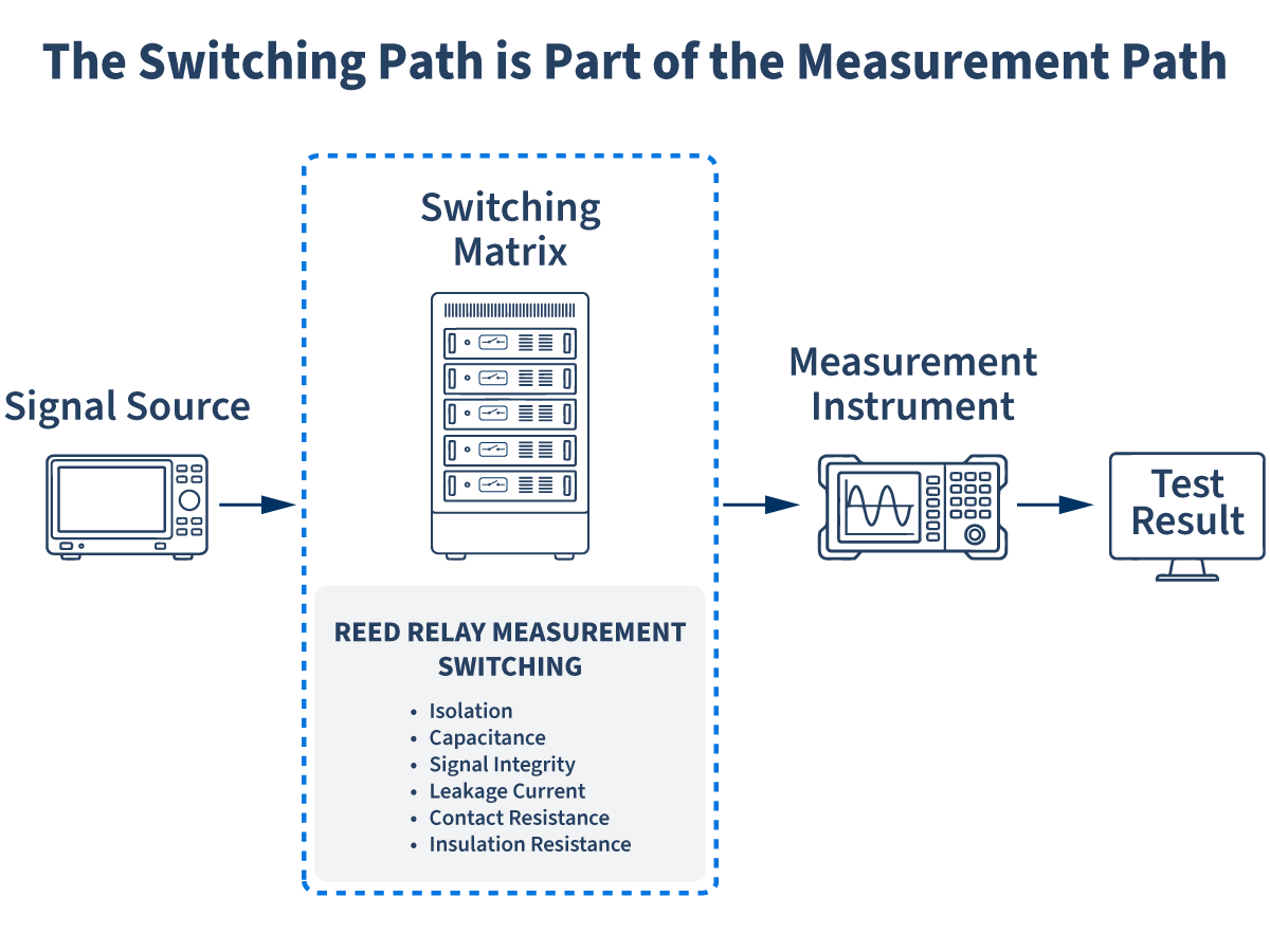
Often Overlooked. Always Involved.
In relay-based measurement systems, signals routed through the switching architecture can be influenced by the electrical characteristics of the relays.
Jump to: Introduction | When Relay Parameters Become Measurement Parameters | Designing for Predictable Electrical Behavior | Aligning Relay Performance with Measurement Needs | From Component Performance to System Performance | From Measurement Challenge to Switching Solution | Go Beyond Components: Validate Your RF Signal Path
When Relay Parameters Become Measurement Parameters
Selecting a relay by switching voltage, current and contact configuration is often only the starting point. Once the relay becomes part of a precision measurement path, characteristics that might look secondary on a datasheet can directly influence the accuracy and repeatability of the measurement.
Below is an overview of a few significant parameters to consider when choosing a relay:
Low leakage current:
This is especially important in insulation or high-impedance measurements, where the instrument may be designed to detect extremely small currents. Any unintended leakage through the switching network can alter the result, so high insulation resistance and low leakage become directly relevant to measurement accuracy and repeatability.
RF capability:
At higher frequencies, the relay must also be considered as part of the transmission path. An open contact is not perfectly open to an RF signal because capacitance still provides a coupling path, while in the closed state the signal is influenced by geometry, impedance transitions, parasitic inductance and shielding. These effects can appear as insertion loss, return loss, reduced isolation or crosstalk, all of which become increasingly important as frequency rises.
Stable contact behavior:
Low-level signals bring another set of requirements because the signal itself may be only a few microvolts. Stable contact resistance and low thermal EMF help preserve such measurements as they pass through the switching network, while resistance variation or unwanted voltage offsets can become significant compared with the signal being measured.
Low capacitance:
Every relay introduces some parasitic capacitance between conductive elements and across an open contact, and in a large switching matrix these small values can accumulate. The result can be longer settling times, additional coupling between channels and, in some cases, a direct impact on how quickly the next reliable measurement can be taken.
High isolation voltage:
In high-voltage test systems, the relay must maintain electrical separation between open contacts, between channels, and where applicable between the switching path and the coil. Sufficient isolation voltage allows the switching network to safely route high test potentials without breakdown or unintended coupling. This becomes particularly important in insulation testing, HiPot systems, and other applications where high voltage and sensitive measurements exist within the same architecture.
Learn how RF-capable reed relays help SoC testers maintain signal integrity, maximize isolation, and ensure accurate routing for multi-GHz and multi-Gbps applications.
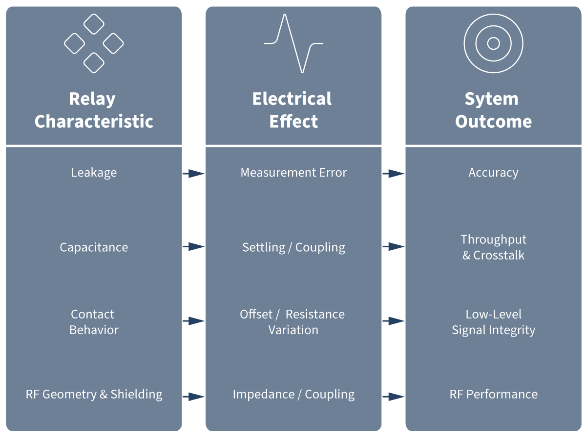
Different relay characteristics influence different aspects of system performance. There is no single “best” relay parameter.
For this reason, there is no single parameter that defines the best relay for a measurement path. What matters is how the switching component behaves within the actual measurement architecture and which electrical characteristics are most important for the application.
Jump to: Introduction | When Relay Parameters Become Measurement Parameters | Designing for Predictable Electrical Behavior | Aligning Relay Performance with Measurement Needs | From Component Performance to System Performance | From Measurement Challenge to Switching Solution | Go Beyond Components: Validate Your RF Signal Path
Designing for Predictable Electrical Behavior
A reed relay might appear simple at first sight, but behind this construction is a careful balance of materials, mechanics, magnetics and electrical design. At its center are two ferromagnetic reed blades sealed inside a glass capsule. A surrounding coil generates the magnetic field that brings the blades together and closes the contact. Add terminals, insulation, packaging and, where required, shielding, and the basic relay structure is complete.
The principle is simple, but ensuring consistent performance across large production volumes is much more demanding. The metal and glass must form a reliable hermetic seal, while contact materials and geometry influence switching behavior, stability and electrical life. The internal atmosphere, typically an inert gas or vacuum, protects the contacts from contamination and contributes to the required switching and isolation characteristics.
Together with suitable contact materials, this enables reliable switching without relying on a cleaning current.
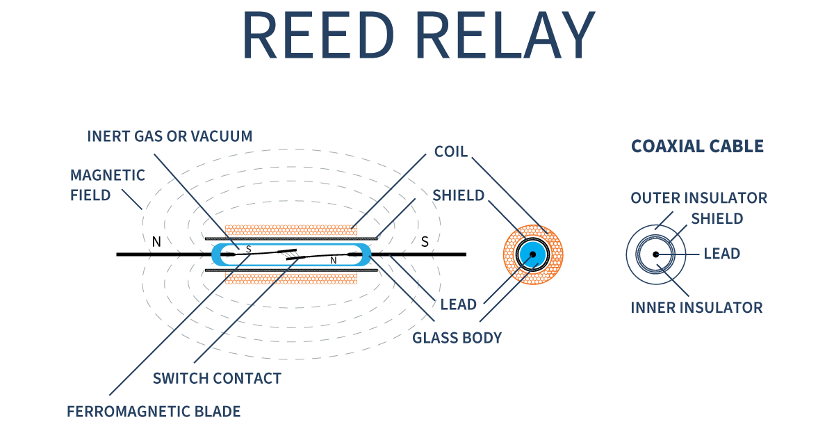
Magnetic and mechanical characteristics must also be tightly controlled. The magnetic properties of the reed blades, spring force, contact gap and mechanical tolerances affect operate and release behavior as well as switching consistency. The balance between magnetic force and mechanical restoring force is therefore fundamental to switch performance and reliability.
Once the reed switch becomes part of a relay, further interactions must be managed. Coil geometry and magnetic efficiency influence actuation, while the position of the switch, coil, terminals and surrounding materials affects capacitance, insulation and coupling. Package design also determines board space, terminal geometry and suitability for dense switching systems.
At higher RF frequencies, another layer of engineering is added because the relay becomes part of the transmission path. Signal-path geometry, terminal arrangement and screening influence impedance, insertion loss, isolation and crosstalk. The goal is to maintain a short, consistent signal path that minimizes parasitic effects and preserves signal integrity.
The goal is to turn this complexity into predictable relay performance that can be integrated confidently into the larger measurement system.
Jump to: Introduction | When Relay Parameters Become Measurement Parameters | Designing for Predictable Electrical Behavior | Aligning Relay Performance with Measurement Needs | From Component Performance to System Performance | From Measurement Challenge to Switching Solution | Go Beyond Components: Validate Your RF Signal Path
Aligning Relay Performance with Measurement Needs
Different Test and Measurement applications place very different demands on the switching path, which means the same relay characteristics do not matter equally in every system.
Precision DAQ
In precision data acquisition, the system may be scanning thermocouples, sensors or other low-level signals, so preserving the measurement as it passes through the switching network becomes the main concern. In this environment, contact stability, thermal behavior and insulation performance can be more important than the maximum switching-power rating.
Semiconductor ATE
Semiconductor ATE presents a different combination of requirements. Systems with many measurement channels require dense switching matrices, while the same platform may need to handle DC parametric measurements, high-speed digital signals and RF signals. Here, the switching architecture has to balance density, settling time, isolation and signal integrity, while controlled geometry, low capacitance and effective shielding become increasingly important as frequency rises.
High-Voltage Test
High-voltage testing brings another set of requirements because the switching network may need to withstand hundreds or thousands of volts while the measurement itself is focused on detecting very small leakage currents. High dielectric strength is therefore only part of the requirement, since insulation resistance, parasitic capacitance, physical spacing, PCB layout and cleanliness all contribute to the performance of the complete measurement path. Creepage and clearance requirements defined by the safety and insulation standards must also be considered at system level.
Learn how to design with high-voltage reed relays
These applications are very different electrically, but the relay design logic remains the same: understand what the system needs to measure, determine how the switching path can influence that measurement, and engineer the relay around those requirements.
Jump to: Introduction | When Relay Parameters Become Measurement Parameters | Designing for Predictable Electrical Behavior | Aligning Relay Performance with Measurement Needs | From Component Performance to System Performance | From Measurement Challenge to Switching Solution | Go Beyond Components: Validate Your RF Signal Path
From Component Performance to System Performance
A modern test system already combines complex measurement electronics, switching architecture, control software and safety requirements. The relay is only one part of that system, but its behavior has to fit the overall design without compromising measurement accuracy, signal integrity or throughput.
This is where application knowledge becomes important. The relay needs to be engineered around the conditions it will actually see, whether that means very small signals, high voltage, dense switching matrices or RF paths. The key is to translate these system requirements into the electrical behavior of the relay, such as the required isolation, capacitance, contact stability, switching capability or RF performance.
These characteristics also interact with each other. Improving one aspect of relay performance can affect another, which means the design is always a balance rather than a matter of maximizing every parameter independently.
That is why effective relay design starts with understanding the application, not only the component specification.
The best relay is not defined by a single specification. It’s defined by how well its electrical behavior supports the requirements of the complete measurement system.
Jump to: Introduction | When Relay Parameters Become Measurement Parameters | Designing for Predictable Electrical Behavior | Aligning Relay Performance with Measurement Needs | From Component Performance to System Performance | From Measurement Challenge to Switching Solution | Go Beyond Components: Validate Your RF Signal Path

From Measurement Challenge to Switching Solution
Standex Detect develops reed relays for a wide range of applications, with Test and Measurement representing one of the most demanding and important areas. Within this field, solutions range from precision and low-level switching to high-voltage, high-density and RF systems.
The starting point is not only the voltage or current rating, but understanding what the measurement path requires from the switching component.
By combining reed-switch technology, magnetic and mechanical design, controlled manufacturing and application knowledge, these requirements can be translated into predictable relay performance.
For the system designer, this means a switching component engineered to fit the measurement architecture, whether the challenge is leakage, capacitance, isolation, signal integrity, switching density or long-term stability.
Good relay design starts with precise measurement and characterization, and ends with a switching component engineered to deliver consistent performance as it becomes part of the measurement path itself.
Designing a switching matrix or measurement path?
Talk with Standex Detect about the switching requirements behind your application.
Jump to: Introduction | When Relay Parameters Become Measurement Parameters | Designing for Predictable Electrical Behavior | Aligning Relay Performance with Measurement Needs | From Component Performance to System Performance | From Measurement Challenge to Switching Solution | Go Beyond Components: Validate Your RF Signal Path
Go Beyond RF Switching Components: Validate Your RF Signal Path
Selecting the right RF relay is only part of the challenge, validating real-world performance is where true system confidence is built.
Standex Detect goes beyond switching components by providing RF evaluation boards designed to accelerate your development process. When operating at multi GHz frequencies, even small discrepancies between modeled and real-world behavior can impact yield and performance.
Our RF demo boards enable engineers to:
- Characterize insertion loss, isolation, and return loss with precision
- Optimize PCB layout and signal routing strategies
- Feed accurate data into simulation and modeling tools
- Accelerate time-to-validation for semiconductor test systems
The result?
Faster design cycles and greater confidence in your final system performance.
RF Demo Board Engineering Guide:
The most successful RF test designs don’t rely on assumptions. They rely on measured data aligned with real-world conditions and that’s exactly what our evaluation boards deliver.
Download the Engineering Guide
Related Articles
-

High-Voltage Insulation Monitoring for Next-Generation BESS
Learn how insulation monitoring helps improve safety, reliability, uptime, and asset protection in Battery Energy Storage Systems (BESS). Explore high-voltage monitoring solutions for 1,000–1,500 VDC energy storage applications.
-

When Standard Sensors Aren’t Enough
Real-world applications rarely operate under ideal conditions. Temperature extremes, fluid exposure, vibration, contamination, and limited installation space can all impact sensing performance and long-term reliability. Learn how custom sensor solutions help overcome these challenges and deliver reliable operation in demanding industrial, transportation, EV, agricultural, and energy applications.
-

Reliable Sensing for Safer, More Efficient EV Systems
Learn how reliable sensing supports safer, more efficient EV systems. Explore applications in battery management, charging systems, fluid monitoring, and safety detection and discover how advanced sensing technologies help improve performance, reliability, and operational safety.
-

Designing High-Density Switching Architectures Without Sacrificing Precision
Learn how engineers can increase channel density while managing capacitance, crosstalk, and PCB design constraints in modern semiconductor test systems.