
Understanding duty cycle and phase angle is essential for achieving accurate speed measurement, direction sensing, and reliable counting in quadrature sensor applications. This guide explains how duty cycle and phase angle affect quadrature sensor performance, how controllers interpret pulse signals, and why proper sensor and target selection are critical for precise motion detection. Whether you’re designing gear tooth sensing systems, rotary encoders, or direction-sensitive monitoring applications, learn the key principles that ensure accurate and dependable results. If you have any questions or would like to discuss your application, please contact our engineering department.
Fundamentals:
Sensors Design and Selection:
What is Duty Cycle & Phase Angle in Quadrature Sensors?
Standex Detect digital pulsing Hall Effect sensors provide square wave outputs that can be connected to meters, PLCs, and other monitoring and controlling devices to resolve speed or count. Quadrature output sensors provide two outputs in a single package that are out of phase for the ability to resolve direction. This application note was created to define duty cycle and phase angle and explain how meters and controllers resolve speed and direction from the pulsing sensor output(s).
Jump to: What is Duty Cycle & Phase Angle in Quadrature Sensors? | Definitions of Duty Cycle & Phase Angle | Why Do Duty Cycle and Phase Angle Matter? | Selecting the Correct Quadrature Sensor for Your Target | Designing Targets for Quadrature Sensors
Definitions of Duty Cycle & Phase Angle
What is Duty Cycle?
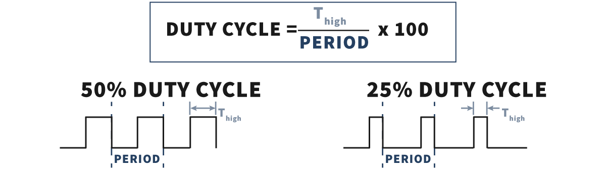
When looking at the digital square wave output, the duty cycle is the percentage of time that the output is in the high state over the period of the square wave. The image below shows the formula for calculating the duty cycle as well as examples of 50% and 25% duty cycle pulse trains.
Application Notes
Sensor Selection Application Notes
Custom Speed Sensors & Direction Dependent Speed Switches
Custom Magnetic Sensor Design and Manufacturing
Guide to Replacing a Speed Sensor
Selecting the Appropriate Hall Effect Sensor and Target Magnet
Why do I need to provide the gear pitch when ordering a Speed and Direction Gear Tooth Sensor?
Target Selection Application Notes
Selection or Design of Sensor Targets
Selecting the Appropriate Hall Effect Sensor and Target Magnet
Sensor Behavior Application Notes
Chopper Stabilization and Gear Tooth Sensors
The Effect of Mounting A Ferrous Metal Sensor in a Steel Sleeve
Understanding Duty Cycle and Phase Angle in Quadrature Sensors
Why Either Pole Hall Switches May Produce 3 Pulses from a Single Magnet
Sensor Output Monitoring Application Notes
How to Hook Up an LED to a Magnetic Sensor
Understanding Duty Cycle and Phase Angle in Quadrature Sensors
Meters and Signal Conditioners
How To Hook Up a Digital Magnetic Sensor to a Relay
Custom Hall Sensor Application Notes
PCBA Manufacturing & Design – Printed Circuit Board Prototyping Services
Thief Hatch Latch Detection Systems
What is Phase Angle?
When looking at Quadrature Sensor Outputs, the phase angle is a measure of the offset between the two pulse trains. When the duty cycles are not both 50%, the entire period needs to be considered in calculating the phase angle. The image below shows an example of 90-degree phase angles with 50% duty cycles compared to 25% duty cycles.
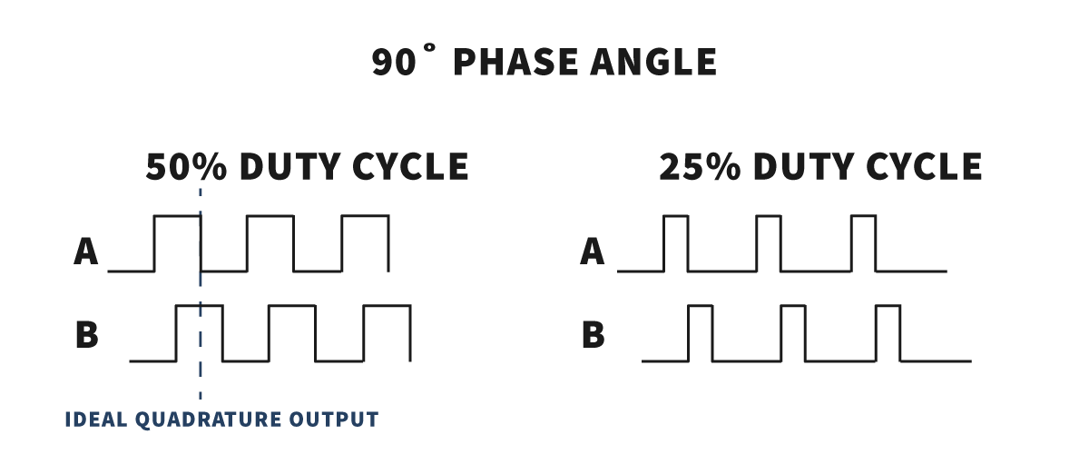
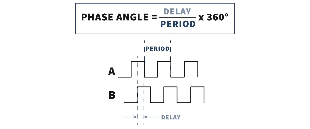
To calculate Phase Angle the delay between the two pulses is measured relative to the period of the pulse. Sensor Solutions measures the delay from the center of the high pulse from channel A to the center of the high pulse from Channel B. The formula for calculating phase angle is shown below.
Jump to: What is Duty Cycle & Phase Angle in Quadrature Sensors? | Definitions of Duty Cycle & Phase Angle | Why Do Duty Cycle and Phase Angle Matter? | Selecting the Correct Quadrature Sensor for Your Target | Designing Targets for Quadrature Sensors
Why Do Duty Cycle and Phase Angle Matter?
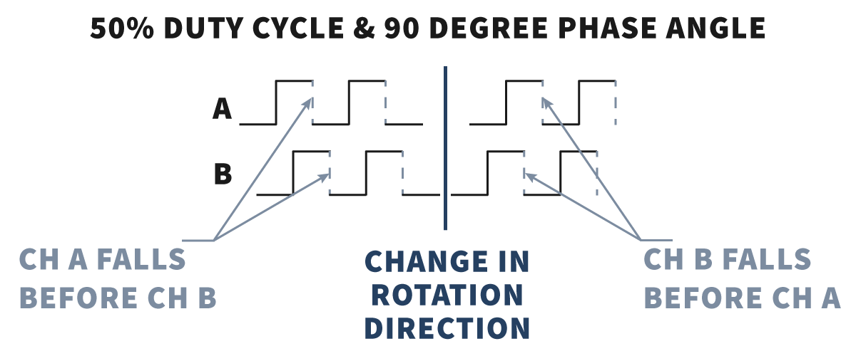
Quadrature sensors are used in direction sensitive counting and speed measurement applications. Meters and control devices look at the two pulse trains to determine the direction of motion. Typically this is done by comparing either the falling or rising edges of the pulses, or comparing one edge against the output state of the other pulse.
Ideal Duty Cycle and Phase Angle
The image below shows a 50% duty cycle with a phase angle of 90 degrees. With this configuration, regardless of where a direction change occurs, or how the controller is resolving direction, the relationship between the falling edges of the pulse ensures notification of direction change on the first pulse.
Note: Although this configuration is ideal, it is extremely difficult to achieve.
Poor Duty Cycle and Ideal Phase Angle
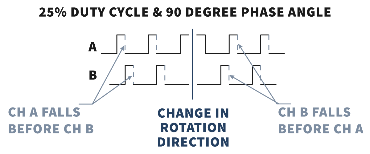
The image below shows a 25% duty cycle with a phase angle of 90 degrees. With this configuration, regardless of where a direction change occurs, a controller resolving direction comparing the falling edges only will always recognize a direction change on the first pulse. However, a meter resolving direction by comparing the rising edge of Channel A to the output state of Channel B may not resolve direction change properly as Channel B is falling during the rise of Channel A.
Ideal Duty Cycle and Poor Phase Angle
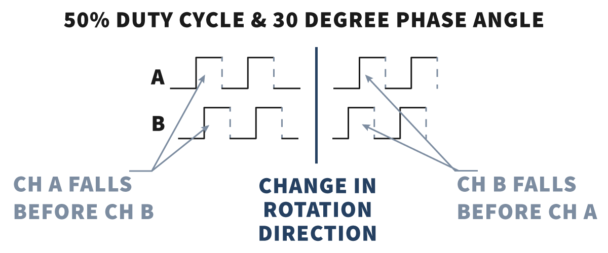
The image below shows a 50% duty cycle with a phase angle of 30 degrees. With this configuration, regardless of where a direction change occurs, a controller will resolve direction properly. However, as the phase angle goes further from 90 degrees, the closer the duty cycle needs to be to 50% to ensure a readable pulse train.
Poor Duty Cycle and Poor Phase Angle
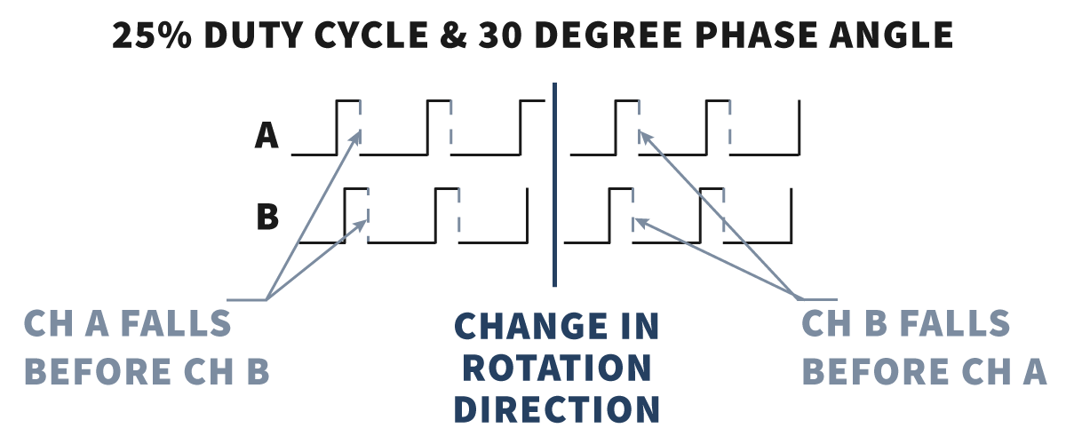
In the real world, most sensor and target combinations will produce a duty cycle greater or less than 50% with a phase angle that is not exactly 90 degrees. The example below shows pulse trains that have both a poor duty cycle and a poor phase angle.
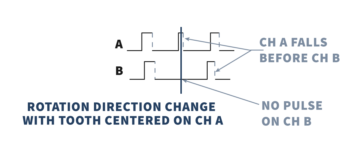
A controller may still resolve direction correctly, but dependent on the position of the tooth when rotation changes, it may not recognize the change in direction until the second tooth passes the sensor. If the meter is counting, this will cause the count to become inaccurate.
Selecting the Correct Quadrature Sensor for Your Target
Many manufacturers claim their quadrature gear tooth detection sensor will work with any standard gear pitch. Although it is true they will provide two out of phase pulse trains, the answer is not that simple. Accurate detection of direction will be dependent on the size of the gear teeth, the distance between them, the distance between the sensing elements within the sensor, and the method the control system calculates direction.
- For direction sensitive speed or count measurement from a gear, tone wheel, or other target with evenly spaced ferrous “teeth” use a True Zero Speed Quadrature Gear Tooth Sensor.
- For direction sensitive speed measurement from targets such as bolt heads, a single hole in a steel disc, or other non-evenly spaced ferrous targets a self-calibrating Quadrature Gear tooth sensor is typically the best choice.
- For direction sensitive speed or count measurement from one or more magnets Sensor Solutions offers Quadrature Hall Switch sensors.
Note: We offer a variety of target magnets, including raw magnets, magnets mounted in bolt heads and clamping shaft collars that can be paired with our sensors for direction-sensitive speed or count measurement.
Contact our engineers today for assistance in determining the best sensor and target combination for your application.
Jump to: What is Duty Cycle & Phase Angle in Quadrature Sensors? | Definitions of Duty Cycle & Phase Angle | Why Do Duty Cycle and Phase Angle Matter? | Selecting the Correct Quadrature Sensor for Your Target | Designing Targets for Quadrature Sensors
Designing Targets for Quadrature Sensors
So, how do you design a target gear to produce a duty cycle near 50%? Although the logical thought is to have your “teeth” the same size as the gap between them, this is not the case. A magnetic field sensor will produce a pulse that is longer in length than the “tooth.” Therefore, to reach a 50% duty cycle the ideal relationship is a smaller tooth with a wider gap between them.
Click here to return the Hall Effect Application Notes page