
Using LEDs with Magnetic Sensors
LEDs can provide a visual indication of the output state from a digital switching magnetic field sensor. LEDs provide a significant amount of light using a small amount of current, so they are nicely suited for use with magnetic sensors. Most LEDs are highly visible with 10mA. Our Hall Effect sensors are typically rated to sink or source at least 20mA, so this will not exceed their capability.
It can be confusing how to connect an LED to a sensor output. LEDs require current to flow in a specific direction, and the amount of current must be limited to prevent damage to both the LED and sensor. The correct wiring method depends on the sensor output type, such as NPN (current sinking), PNP (current sourcing), open collector, or TTL (0 to 5V) outputs.
Understanding LED Polarity and Current Flow
Determining the Direction of Current Flow
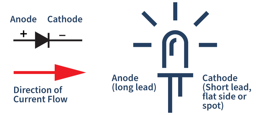
LEDs have an anode and a cathode, sometimes labeled with a + and − symbol. For the LED to illuminate, current must flow from the positive anode (+) to the negative cathode (−).
Selecting a Current-Limiting Resistor
Why LEDs Require a Series Resistor
The current flowing through an LED must be limited using a series resistor. Without proper current limiting, excessive current can damage the LED and potentially the sensor output.
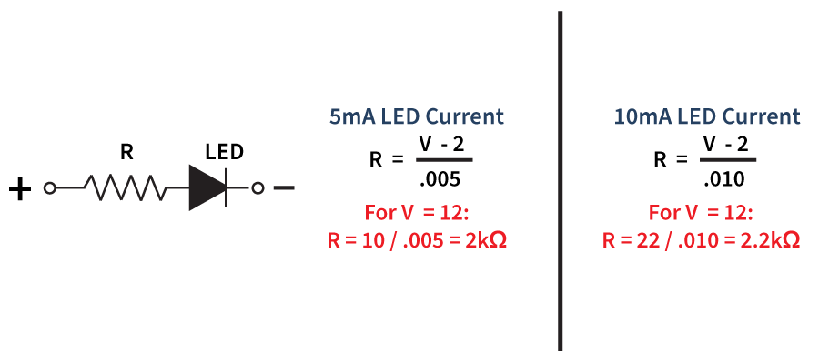
Most LEDs are quite bright at currents between 5 mA and 10 mA. At these current levels, the voltage drop across a typical LED is approximately 2 volts.
Calculating the Correct Resistor Value
The current through the resistor can be calculated using Ohm’s Law:
Current = Voltage ÷ Resistance
For LEDs without a built-in resistor, use the appropriate supply voltage and desired LED current to determine the correct resistor value. Use the formulas to the right to determine the appropriate resistor size.
Using LEDs with Built-In Resistors
Some LEDs are available with integrated series resistors. These products are typically specified by their operating voltage range, eliminating the need for external resistor calculations.
Application Notes
Sensor Selection Application Notes
Custom Speed Sensors & Direction Dependent Speed Switches
Custom Magnetic Sensor Design and Manufacturing
Guide to Replacing a Speed Sensor
Selecting the Appropriate Hall Effect Sensor and Target Magnet
Why do I need to provide the gear pitch when ordering a Speed and Direction Gear Tooth Sensor?
Target Selection Application Notes
Selection or Design of Sensor Targets
Selecting the Appropriate Hall Effect Sensor and Target Magnet
Sensor Behavior Application Notes
Chopper Stabilization and Gear Tooth Sensors
The Effect of Mounting A Ferrous Metal Sensor in a Steel Sleeve
Understanding Duty Cycle and Phase Angle in Quadrature Sensors
Why Either Pole Hall Switches May Produce 3 Pulses from a Single Magnet
Sensor Output Monitoring Application Notes
How to Hook Up an LED to a Magnetic Sensor
Understanding Duty Cycle and Phase Angle in Quadrature Sensors
Meters and Signal Conditioners
How To Hook Up a Digital Magnetic Sensor to a Relay
Custom Hall Sensor Application Notes
PCBA Manufacturing & Design – Printed Circuit Board Prototyping Services
Thief Hatch Latch Detection Systems
Special Considerations for -RT Output Sensors
It is not recommended to use an LED with the -RT option unless the LED is the only load connected to the output.
The -RT sensor requires the LED to sink current to ground. Note that a 499-ohm resistor is already present in the circuit, and the supply voltage is 5 volts. LED current can be calculated as:
I LED = (5-2) / (499 + R)
For approximately 5mA of LED current, usa a 100-ohm resistor.
Important Performance Considerations
When using an LED with an -RT output, the output high voltage (VOH) will be significantly lower than 5V. As a result, the sensor may not be able to drive additional loads reliably.
In this configuration, the LED will be ON when the sensor output is OFF.

Talk to one of our Engineers. We have years of experience in designing custom Hall Effect sensors for new applications as well as OEM replacements. Contact out Engineering Department today to discuss your specific needs.
Click here to return the Hall Effect Application Notes page