
Overview of Selecting the Appropriate Hall Effect Sensor and Target Magnet:
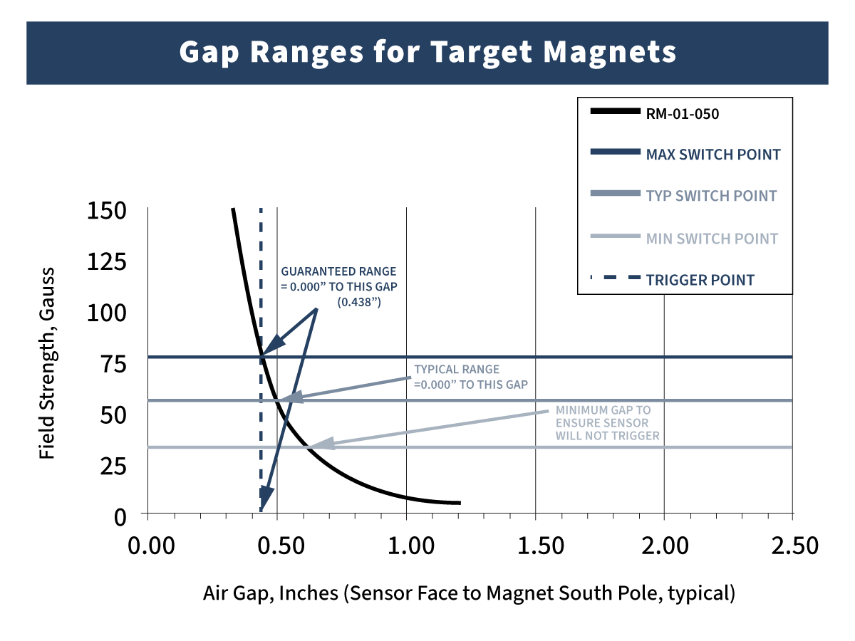
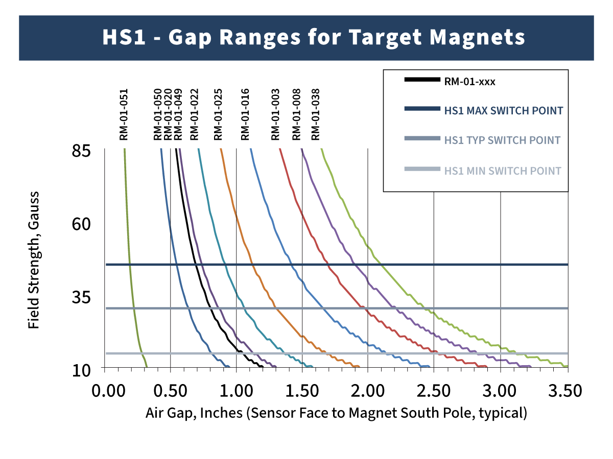
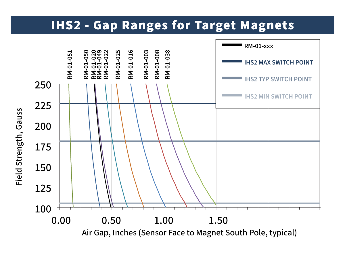
Charts in this application note indicate the typical gap ranges that our Hall Effect Switches will detect target magnets available on our website. All curves and switch points are based on the sensing element location in a typical housing and the calculated magnetic field strengths.
Using the Charts:
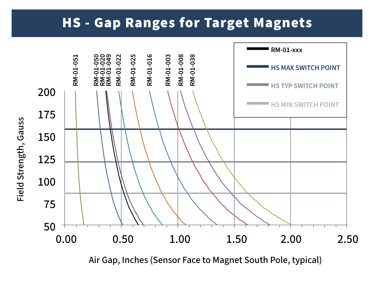
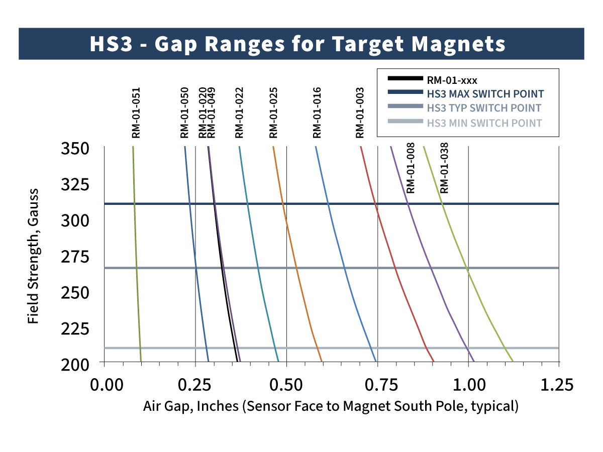
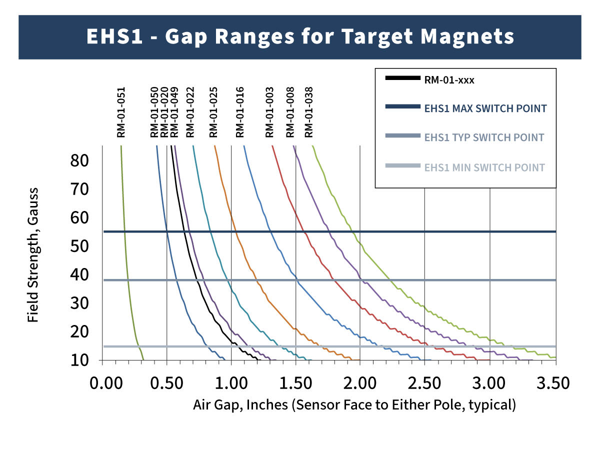
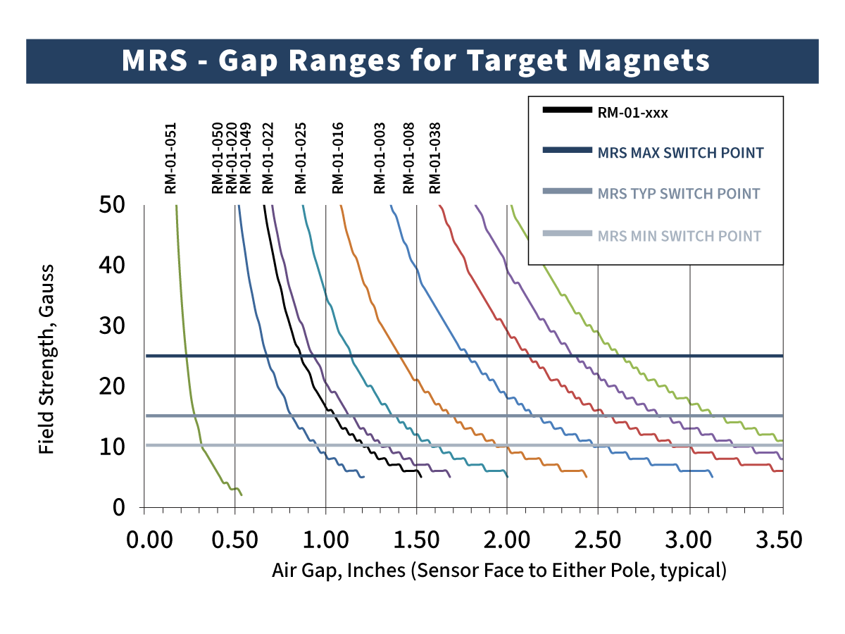
Each chart shows the typical output curve of the field produced by the South Pole of multiple magnets at room temperature. The upper horizontal line indicates the worst case for the sensor type to switch (max switch point or highest possible field required). The middle line indicates the typical switch point for the sensor. The lowest line indicates the smallest possible field that could potentially trigger the sensor (min switch point).
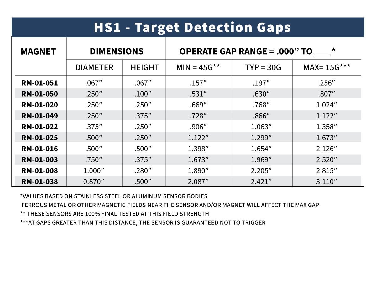
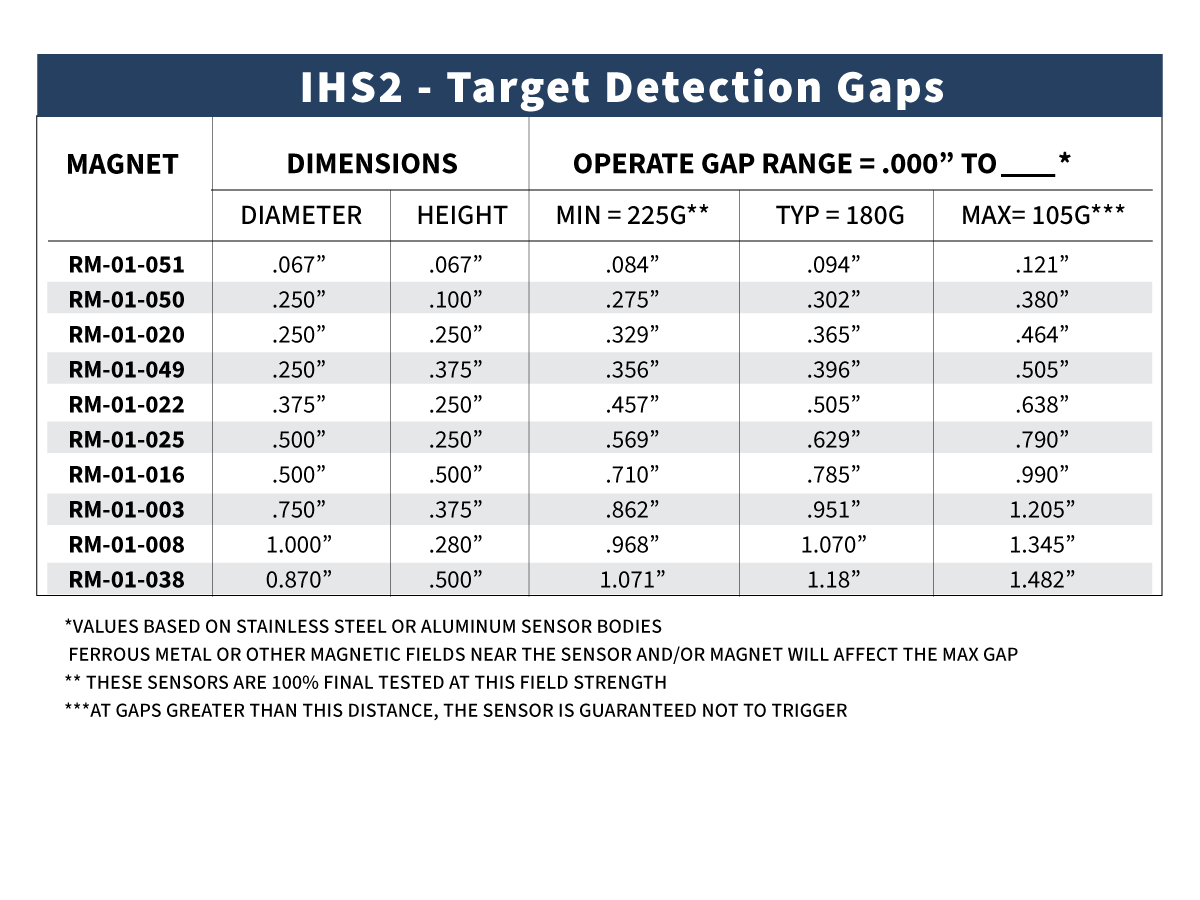
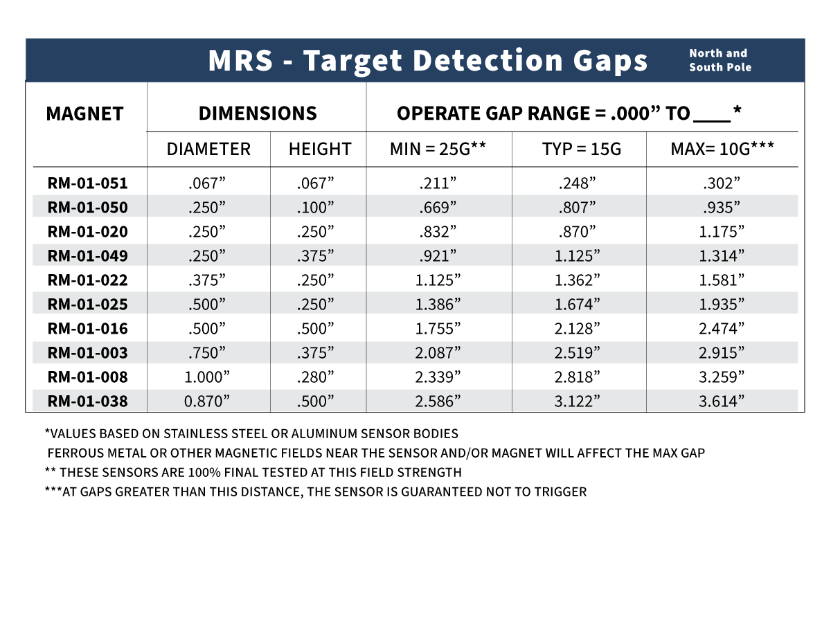
Sensors are 100% tested to switch at the max switch point, but most will operate closer to the typical switch point. The guaranteed range* that a given sensor will detect a specific magnet will be from a gap of 0.000” to the point where the curve reaches the max switch point. The minimum gap required to ensure that the sensor will not trigger the magnet is the below where the curve crosses the min switch point.
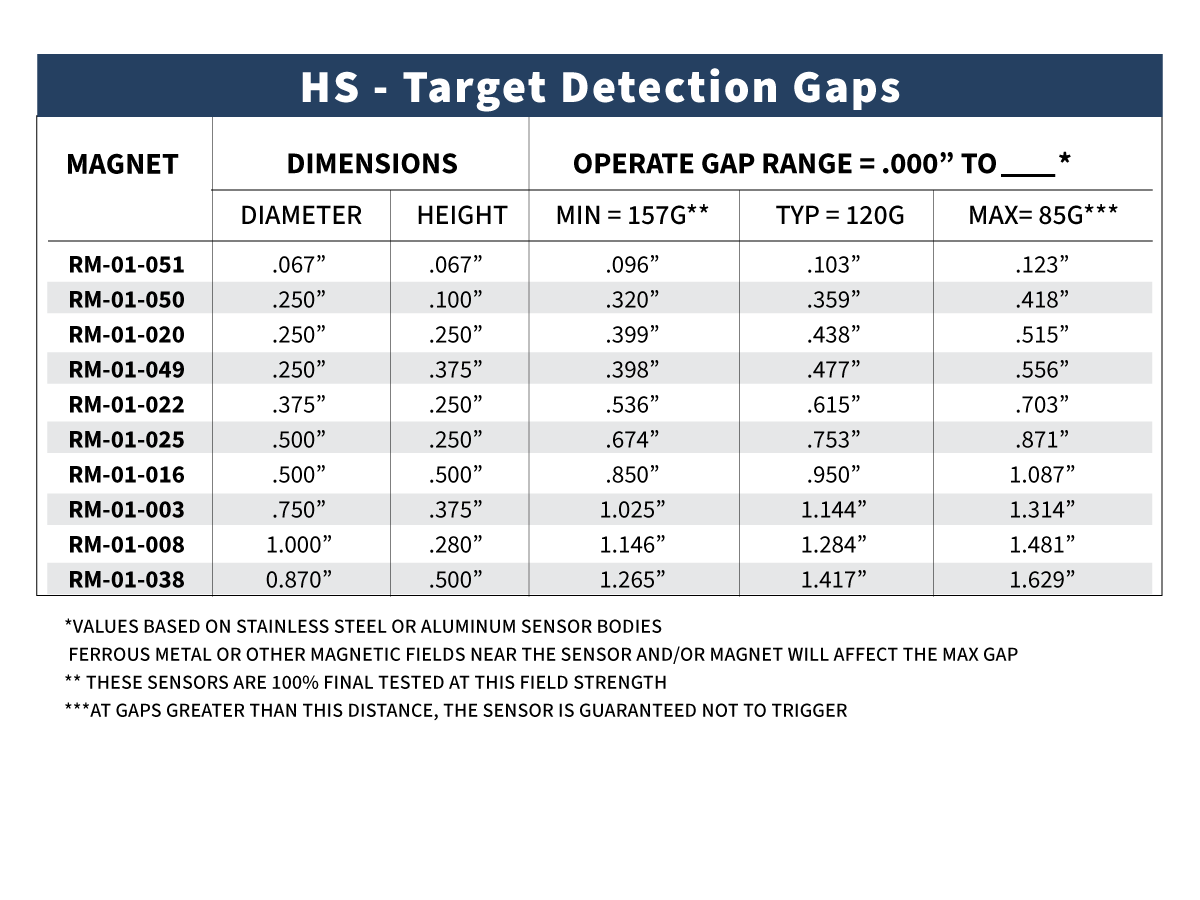
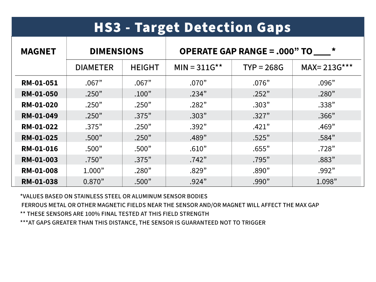
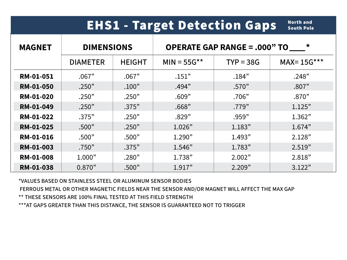
Below each chart is a table indicating the max, typical, and min switch point for the sensor and each magnet type listed.
Application Notes
Sensor Selection Application Notes
Custom Speed Sensors & Direction Dependent Speed Switches
Custom Magnetic Sensor Design and Manufacturing
Replacing a Speed Sensor is not Easy
Selecting the Appropriate Hall Effect Sensor and Target Magnet
Why do I need to provide the gear pitch when ordering a Speed and Direction Gear Tooth Sensor?
Target Selection Application Notes
Selection or Design of Sensor Targets
Selecting the Appropriate Hall Effect Sensor and Target Magnet
Sensor Behavior Application Notes
Chopper Stabilization and Gear Tooth Sensors
The Effect of Mounting A Ferrous Metal Sensor in a Steel Sleeve
Understanding Duty Cycle and Phase Angle in Quadrature Sensors
Why either Pole Hall Switches may produce 3 pulses from a single mant
Sensor Output Monitoring Application Notes
How to Hook Up an LED to a Magnetic Sensor
Understanding Duty Cycle and Phase Angle in Quadrature Sensors
Meters and Signal Conditioners
How To Hook Up a Digital Magnetic Sensor to a Relay
Custom Solutions Application Notes
PCBA Manufacturing & Design – Printed Circuit Board Prototyping Services
Thief Hatch Latch Detection Systems
*Magnetic fields will be affected by the presence of steel or other magnets. Standex Detect recommends testing any given magnet and sensor combination in the application to determine installation gaps. Non standard housings may also position the sensing element closer to or farther from the magnet surface.
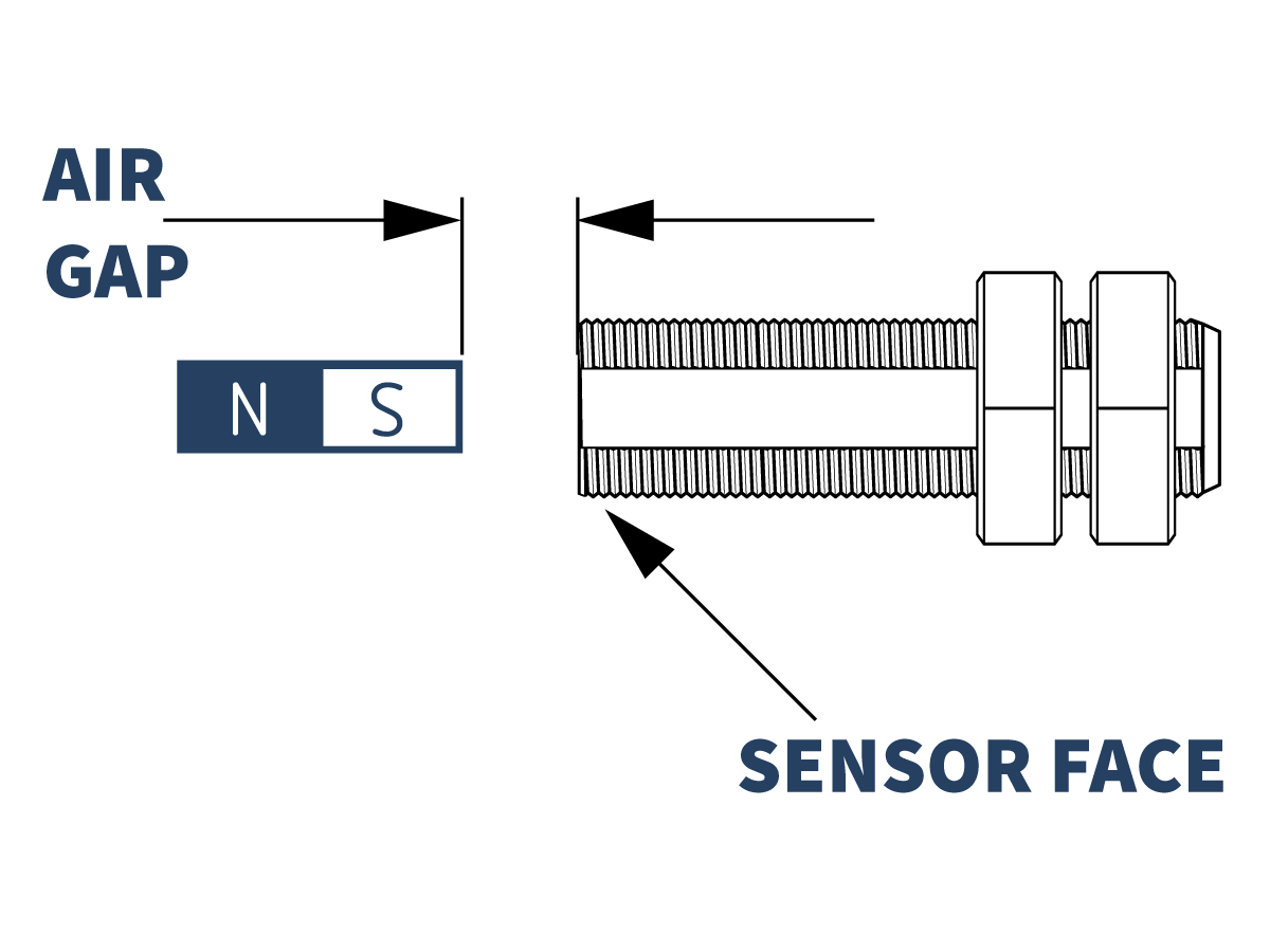
Measuring Air Gap
This figure shows how the air gap is measured between a sensor and target magnet for the charts and data in this Application note.
Charts
Each chart lists common Neodymium Cylinder Magnets available from Standex Detect. Data for other magnets is available upon request.
Click the tab below to see the sensitivity of the sensor and max gap data for each characteristic.
HS / HSQ / HSCD / DHS / DHSS
The HS element used in the above sensors switches between 85-157 Gauss, with a typical switch point of 120 Gauss.
HS1 / HS1Q / HS1CD / DHS1 / DHSS1
The HS1 element used in the above sensors switches between 15-45 Gauss, with a typical switch point of 30 Gauss.
IHS2 / IHS2Q / IHS2CD / DIHS2 / DIHSS2
The IHS2 element used in the above sensors switches between 105-222 Gauss, with a typical switch point of 180 Gauss.
HS3 / HS3Q / HS3CD / DHS3 / DHSS3
The HS3 element used in the above sensors switches between 213-311 Gauss, with a typical switch point of 268 Gauss.
EHS1 / EHS1Q / EHS1CD
The EHS1 element used in the above sensors switches between 15-55 Gauss, with a typical switch point of 38 Gauss.
MRS /MRQ / MRCD
The MRS element used in the above sensors switches between 10-25 Gauss, with a typical switch point of 15 Gauss.
If the sensor characteristic or target magnet you are looking for is not located in this document, contact our Engineering Department to discuss your specific requirements.
Click here to return the Hall Effect Application Notes page