
Test Summary
The 275VPA and 275VPD Hall Effect Ferrous Metal Proximity Sensors both have the same magnetic structure. The intended use is to detect ferrous metal in front of the sensing face. The 275VPD sensors indicate when a steel target is within a specified gap range of the sensor. The 275VPA sensor provides an analog output relative to the gap between the sensor and a ferrous target.
These sensors are also affected by the presence of ferrous metal behind the sensing tip. How much effect the ferrous metal has on the sensor depends on how close the ferrous metal is to the permanent magnet within the sensor.
To measure this effect, tests were performed where sensors were mounted centered in a variety of diameter steel sleeves and the output was monitored as the setback distance between the sensor face and the edge of the steel tube decreased until the sensor face was flush with the steel tube.
Increasing the diameter of the sleeve simulates increasing the bore diameter surrounding the sensor when it is mounted through a steel enclosure.
Testing Method
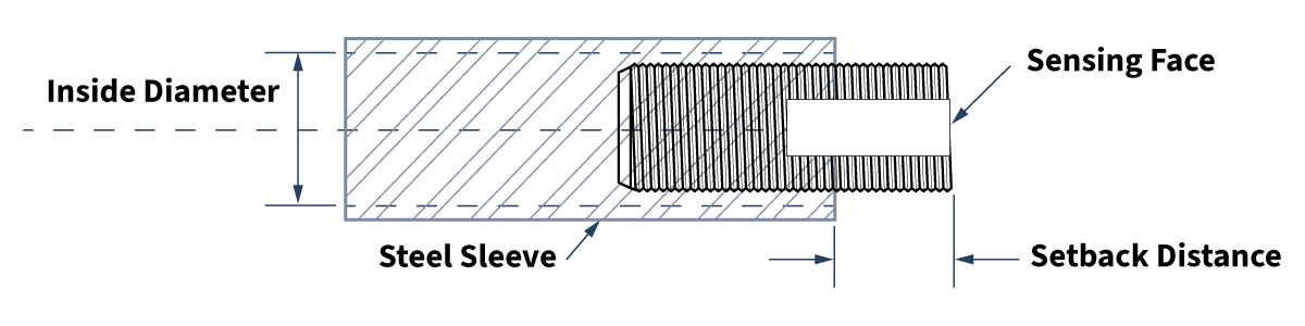
We tested 4 different sleeves, and broke the effect into 4 categories depending on how they affected our standard programmed options:
Sensors Tested
Standard 275VPD Digital Sensor
- 900-13-000 programming
- Programmed to detect a steel plate at 0.375"
Standard 275VPA Analog Sensor
- 900-12-000 programming
- Programmed to provide a 0-5V output as the gap goes from 0.000" to infinity
Output Categories
Category 1
Turns a 275VPD digital sensor on, changes the 275VPA analog sensor by 100mV.
Category 3
Has very little effect on the 275VPD digital sensor, changes the 275VPA analog sensor by 10mV.
Category 2
Has a noticeable effect on the 275VPD digital sensor, changes the 275VPA analog sensor by 50mV.
Category 4
Has no noticeable effect on the 275VPD digital sensor, changes the 275VPA analog sensor by 3mV.
| Tube Diameter | Category 1 | Category 2 | Category 3 | Category 4 |
|---|---|---|---|---|
| 0.628″ |  .325" .325" |  .475" .475" | .750" |  1.00" 1.00" |
| 0.628″ | .100" | .325" | .750" | 1.00" |
| 1.05″ | n/a* | .000" | .750" | 1.30" |
| 2.60″ | n/a* | n/a* | n/a* | n/a* |
*Has no effect on 275VPD output with sensor face flush to steel (no setback)
Recommendations
- If you are mounting the sensor in ferrous steel with an inside diameter less than ~1.5" and want the steel to have VERY LITTLE EFFECT (Cat 3), make sure the sensor sticks out at least .750".
- Using a Setback Distance less than the Cat 2 values will make the sensor very sensitive (may turn on).
- If your inside diameter is greater than ~2", it will have very little effect no matter where it is installed.
- If you have to mount the sensor with a Setback Distance of less than .750", it is suggested that you request a custom programming.
Application Notes
Sensor Selection Application Notes
Custom Speed Sensors & Direction Dependent Speed Switches
Custom Magnetic Sensor Design and Manufacturing
Guide to Replacing a Speed Sensor
Selecting the Appropriate Hall Effect Sensor and Target Magnet
Why do I need to provide the gear pitch when ordering a Speed and Direction Gear Tooth Sensor?
Target Selection Application Notes
Selection or Design of Sensor Targets
Selecting the Appropriate Hall Effect Sensor and Target Magnet
Sensor Behavior Application Notes
Chopper Stabilization and Gear Tooth Sensors
The Effect of Mounting A Ferrous Metal Sensor in a Steel Sleeve
Understanding Duty Cycle and Phase Angle in Quadrature Sensors
Why Either Pole Hall Switches May Produce 3 Pulses from a Single Magnet
Sensor Output Monitoring Application Notes
How to Hook Up an LED to a Magnetic Sensor
Understanding Duty Cycle and Phase Angle in Quadrature Sensors
Meters and Signal Conditioners
How To Hook Up a Digital Magnetic Sensor to a Relay
Custom Hall Sensor Application Notes
PCBA Manufacturing & Design – Printed Circuit Board Prototyping Services
Thief Hatch Latch Detection Systems
Talk to one of our Engineers. We have years of experience in designing custom Hall Effect sensors for new applications as well as OEM replacements. Contact out Engineering Department today to discuss your specific needs.
Click here to return the Hall Effect Application Notes page