
Overview
The following application notes are for use in selecting or designing targets for use with our Hall Effect Gear Tooth Sensors. If you have any questions or would like to discuss your application, please contact our engineering department.
Terms and Definitions:
Target Selection and Design:
Calibration/Testing Sensors for Custom Targets:
What is the Diametral Gear Pitch and Why Does It Matter?
The diametral pitch determines whether two different size gears can be mated together and is calculated using the relationship between the number of teeth on the gear and the diameter of the gear in inches. The distance between gear teeth remains constant as the diameter, size, and number of teeth increase/decrease.
Hall Effect Gear Tooth sensors are measuring the change in a magnetic field introduced by the presence of the ferrous gear teeth. Single channel gear tooth sensors are designed to detect 4-32 pitch gears. Quadrature and Speed/Direction sensors contain two sensing elements and direction is resolved by comparing the output states and/or edges of the sensor pulses. In order to provide accurate direction resolution, these sensing elements are spaced within the sensor to ensure the outputs are as close to 90 degrees out of phase as possible.
Jump to: Diametral Gear Pitch | Orienting & Aligning Sensors | Gear Selection | End Sensing | Face Sensing | Detecting Bolt Heads | Sensor Calibration | Gear Requirements | Example Custom Targets
Orienting and Aligning Sensors Relative To the Target Gear
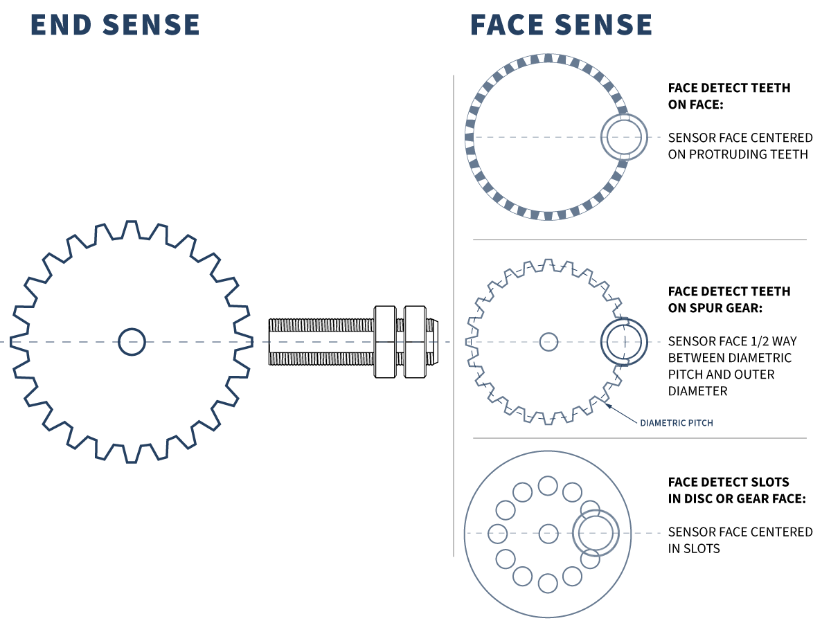
The image below shows the difference between sensing a gear from the end and the face and indicates where to install the sensor relative to the target. Sensor orientation requirements are defined in the sensor Specifications sheet.
Application Notes
Sensor Selection Application Notes
Custom Speed Sensors & Direction Dependent Speed Switches
Custom Magnetic Sensor Design and Manufacturing
Replacing a Speed Sensor is not Easy
Selecting the Appropriate Hall Effect Sensor and Target Magnet
Why do I need to provide the gear pitch when ordering a Speed and Direction Gear Tooth Sensor?
Target Selection Application Notes
Selection or Design of Sensor Targets
Selecting the Appropriate Hall Effect Sensor and Target Magnet
Sensor Behavior Application Notes
Chopper Stabilization and Gear Tooth Sensors
The Effect of Mounting A Ferrous Metal Sensor in a Steel Sleeve
Understanding Duty Cycle and Phase Angle in Quadrature Sensors
Why either Pole Hall Switches may produce 3 pulses from a single mant
Sensor Output Monitoring Application Notes
How to Hook Up an LED to a Magnetic Sensor
Understanding Duty Cycle and Phase Angle in Quadrature Sensors
Meters and Signal Conditioners
How To Hook Up a Digital Magnetic Sensor to a Relay
Custom Solutions Application Notes
PCBA Manufacturing & Design – Printed Circuit Board Prototyping Services
Thief Hatch Latch Detection Systems
Recommendations for Selecting Gears
Hall Effect gear tooth sensors can detect a wide variety of targets. Space constraints, resolution/scaling requirements, or shaft size may be the driving factor in determining a target gear form factor that will work in your application. We calibrate and test our standard sensors using 14.5° pressure angle steel spur gears and offers several spur gear options on our website. We can also source additional gears, contact us to discuss your requirements.
If your application will require the sensor to target a rack, helical, involute, or other gear types, contact our engineers to discuss which of our sensors will provide the best output from the target, or if custom calibration may be required.
Jump to: Diametral Gear Pitch | Orienting & Aligning Sensors | Gear Selection | End Sensing | Face Sensing | Detecting Bolt Heads | Sensor Calibration | Gear Requirements | Example Custom Targets
Designing End Sensing Target Gears
If your application is going to require a custom end sensed target, consider the following in your design.
Number of Pulses Per Revolution
If you are only looking for one pulse per revolution or will not have evenly spaced “teeth” be sure to choose a sensor type built with our “target tracker” sensing elements. 18ADSO and 37ADSO options will provide a single pulsing output. For two out-of-phase outputs choose our 37ADQO option. For a pulsing output and a direction dependent output we have the 37ADSDO option.
For greater resolution, you can increase the number of teeth.
If you are looking to display the speed in RPM, but cannot scale your display, design your target to have 60 teeth.
Note: As the gear teeth get closer to each other the maximum air gap the sensor can detect the teeth will decrease.
The Size of the Teeth as Compared to the Gap Between Them
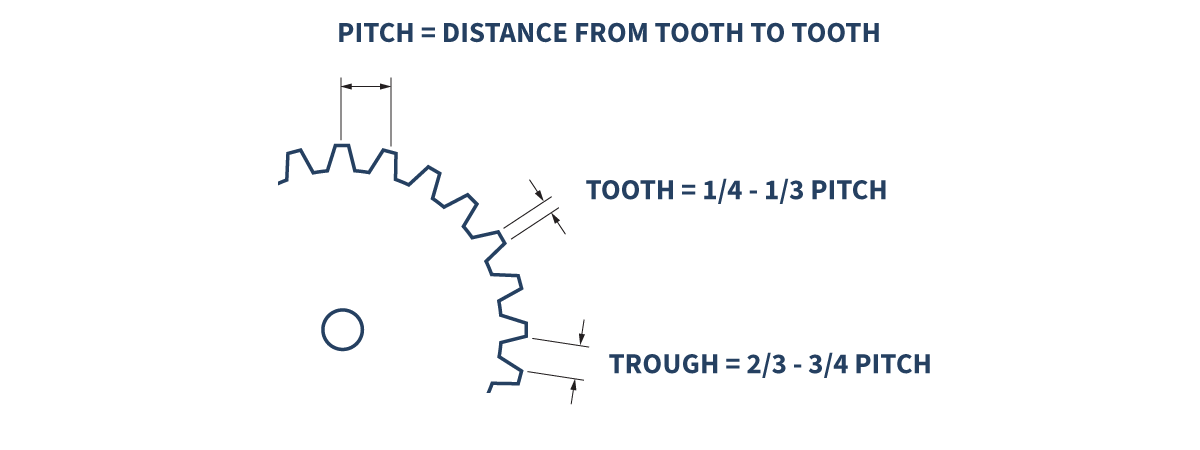
To provide a sensor output wave form with a duty cycle close to 50%, the gap between the teeth needs to be larger than the tooth itself. This is because the sensor element detects the gear tooth before it reaches the sensing element, and after the tooth has passed.
The Shape of the Gear Teeth
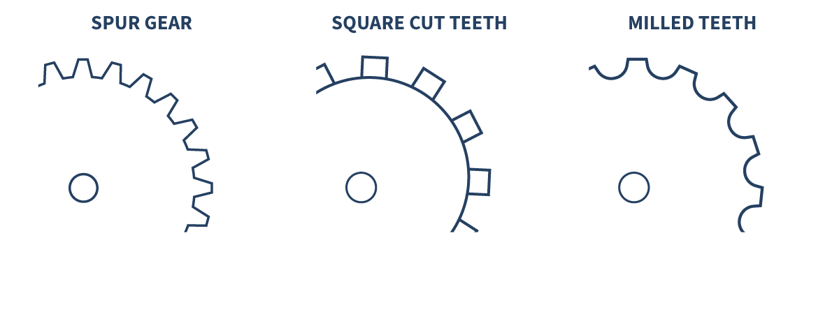
Gear tooth sensors are capable of detecting teeth that are cut with a pressure angle such as spur gears, square cut teeth, or milled teeth with rounded troughs.
The thickness of the gear should also be considered for end sensing targets. Although gears thinner than 1/4 inch thick can be detected, the maximum operate gap will decrease as the gear becomes thinner.
The height of the tooth (distance between the top of the tooth and the bottom of the trough) needs to be great enough to ensure that the sensor output turns off between the teeth. The minimum height is dependent on pitch of the target gear. As the pitch becomes finer, the maximum detection gap decreases. As a rule of thumb it is recommended that the minimum tooth height should be greater than the typical max gap defined on the specifications sheet target performance.
Materials
Hall Effect Gear tooth sensors detect gears by measuring the change to an internal magnetic structure when a tooth is in front of the sensor. The iron content of the gear will determine how close the sensor face will need to be to the passing gear tooth in order to detect it. If the material will attract and hold a magnet, then it can be sensed with a Hall Effect Gear Tooth Sensor.
If you have questions regarding a target being designed for an application, or would like to have an applications engineer review your design, contact us.
Designing Face Sensing Target Gears
If your application is going to require a custom face sensed target, consider the following in your design.
Number of Pulses Per Revolution
If you are only looking for one pulse per revolution or will not have evenly spaced “teeth” be sure to choose a sensor type built with our “target tracker” sensing elements. 18ADSO and 37ADSO options will provide a single pulsing output. For two out-of-phase outputs choose our 37ADQO option. For a pulsing output and a direction dependent output we have the 37ADSDO option.
If you are looking for more resolution, you can increase the number of teeth or holes in the target.
If you are looking to display the speed in RPM, but cannot scale your display, design your target to have 60 teeth.
Note: As the gear teeth get closer to each other the maximum air gap the sensor can detect the teeth will decrease.
The Size of the Teeth as Compared to the Gap Between Them
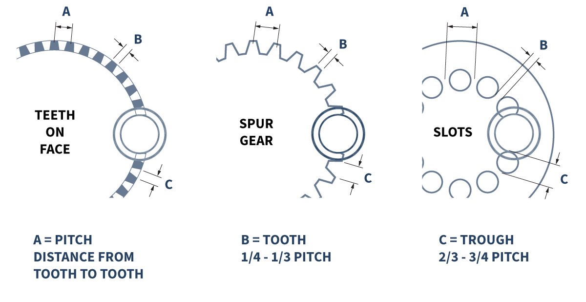
To provide a sensor output wave form with a duty cycle close to 50%, the gap between the teeth needs to be larger than the tooth itself. This is because the sensor element detects the gear tooth before it reaches the sensing element, and after the tooth has passed.
Note: When your target consists of one or more holes cut into steel, the “tooth” is the material between the holes.
The Shape of the Gear Teeth or Holes Cut Into a Solid Target
When face sensing a spur gear target the teeth need to be tall enough that the sensor can be located in a position where it sees each tooth, but not too close to the body of the gear that the sensing element is always seeing the gear. If you are unsure if the teeth are large enough, contact us to speak to an engineer.
When the target consists of holes cut into a steel disk or cylinder, it is recommended to cut the hole wider than the diameter of the sensor to ensure the sensing element output turns off while passing the hole.
The thickness of the gear should also be considered for end sensing targets. Although gears thinner than 1/4 inch thick can be detected, the maximum operate gap will decrease as the gear becomes thinner.
The height of the tooth (distance between the top of the tooth and the bottom of the trough) needs to be great enough to ensure that the sensor output turns off between the teeth. The minimum height is dependent on pitch of the target gear. As the pitch becomes finer, the maximum detection gap decreases. As a rule of thumb it is recommended that the minimum tooth height should be greater than the typical max gap defined on the specifications sheet target performance.
Materials
Hall Effect Gear tooth sensors detect gears by measuring the change to an internal magnetic structure when a tooth is in front of the sensor. The iron content of the target will determine how close the sensor face will need to be in order to detect it. If the material will attract and hold a magnet, then it can be sensed with a Hall Effect Gear Tooth Sensor.
If you have questions regarding a target being designed for an application, or would like to have an applications engineer review your design, contact us.
Detecting Bolt Heads and Other Ferrous Protrusions
In some applications it is not practical or possible to attach a target gear for speed measurement. Hall Effect Sensors built with our “target tracker” technology are capable of detecting features such as steel bolt heads that already exist or can be added to the object you are attempting to measure the speed, count, or position of.
18ADSO and 37ADSO options will provide a single pulsing output. For two out-of-phase outputs choose our 37ADQO option. For a pulsing output and a direction dependent output we have the 37ADSDO option.
Jump to: Diametral Gear Pitch | Orienting & Aligning Sensors | Gear Selection | End Sensing | Face Sensing | Detecting Bolt Heads | Sensor Calibration | Gear Requirements | Example Custom Targets
Will Your Target Require Custom Sensor Calibration?
Applications for Measuring Speed
Our single channel gear tooth sensors are calibrated to detect common spur gears with diametral pitches ranging from 4 to 24. These sensors require an orientation to the direction of the motion of the target gear. These true zero speed sensors will provide 1 pulse per tooth regardless of how slow the target is moving. If you are designing a custom target that follows the guidelines for designing End Sensing target gears above, the target will work well with standard sensor calibration.
Our Target Tracker single channel gear tooth sensors are self calibrating for detection of gears with unevenly spaced teeth and for detecting targets such as bolt heads. These sensors do not require a specific orientation to the target and can be used with standard spur gears as well as unique targets. They are not “true zero” speed sensors but have been proven to accurately detect targets below 0.1 Hz.
Need Assistance? If you have any questions, contact us to discuss the details of your target with an applications engineer.
Applications for Measuring Speed and Direction
Determining direction as well as speed involves the comparison of two sensing elements within the sensor. Sensor outputs can be provided in the form of quadrature pulsing outputs, one pulsing output and a high/low switching direction output, or a combination of a quadrature and direction outputs. To provide a usable output, the design of the target must consider both the distance from “tooth” to “tooth” as well as the relationship between the size of the teeth and the gaps between them.
Standex Detect speed and direction sensors are manufactured and calibrated specific to the target pitch and in some application the target from the application.
Not Sure if You Need Calibration? To determine if your target will be required for calibration, contact us to discuss the details of your target with an applications engineer.
Applications for Counting
To provide an accurate directional count, monitoring devices compare the outputs from a quadrature gear tooth sensor to determine whether the “tooth” detected will increase or decrease the count. Our quadrature gear tooth sensor are manufactured and calibrated specific to the target pitch and in some application the target from the application.
Not Sure if You Need Calibration? To determine if your target will be required for calibration, contact us to discuss the details of your target with an applications engineer.
Requirements for Submitting Gears to Standex Detect
If based on the information above or discussion of your application with one of our engineers it is determined that calibration and testing will require sending a gear to us, please see below.
Test Gear Requirements:
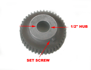
- Unless otherwise approved by our engineers, gears should be mounted to a 1/2″ set screw hub.
- Target gears must be properly balanced when mounted to allow for high speed operation.
- Target gears when mounted should provide a consistent gap from each tooth to the sensor face when spinning
- If known, please provide typical operating speeds the sensor will be measuring in the application and the desired air gap range
Jump to: Diametral Gear Pitch | Orienting & Aligning Sensors | Gear Selection | End Sensing | Face Sensing | Detecting Bolt Heads | Sensor Calibration | Gear Requirements | Example Custom Targets
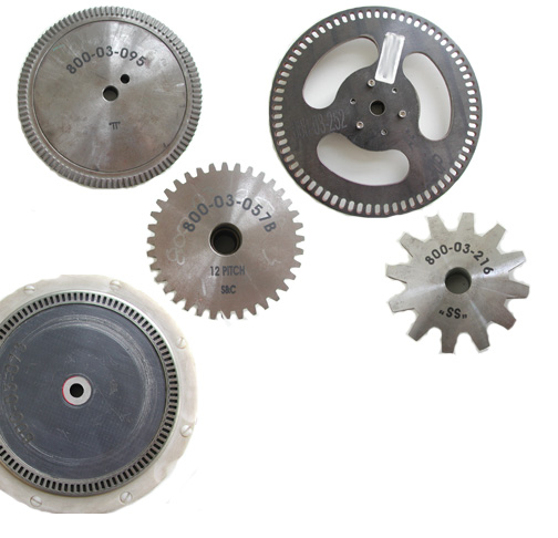
Example Custom Targets
The image below is just some examples of custom gears that Standex Detect builds, calibrates, and test with for customer applications.
Contact us if you would like to discuss options and requirements for your application.
Jump to: Diametral Gear Pitch | Orienting & Aligning Sensors | Gear Selection | End Sensing | Face Sensing | Detecting Bolt Heads | Sensor Calibration | Gear Requirements | Example Custom Targets
If the sensor characteristic or target magnet you are looking for is not located in this document, contact our Engineering Department to discuss your specific requirements.
Click here to return the Hall Effect Application Notes page