
What is the Chopper Stabilization?
Chopper stabilization is an electronic offset correction technique used on many Hall Effect sensors. The Hall Effect bridge element is sensitive to both magnetic fields, and to mechanical stresses put on the element. Mechanical stresses can come from molding the element into its IC package, bending the leads, heating the chip, potting, pressure put on the sensor face, etc. Chopper stabilization is a switching technique that sends current in one direction of the hall bridge and measuring the output, then sending current in the other direction and measuring the output. When these 2 outputs are averaged, the result corrects for the error that comes from the mechanical stresses. This switching occurs at a high speed, called the Chopper Switching Frequency. The outputs need to be turned off during this switching time. They are then updated at the end of the cycle.
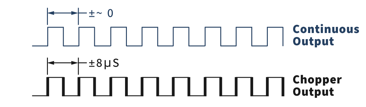
What a customer will notice is that with an instantaneous change in the magnetic field, the output may take up to 1 / Chopper Frequency to update. For a typical 62k Hz Chopper Frequency, the output will take up to 16uS to change. At low speeds, this 16uS ‘noise’ is a tiny percentage. At higher speeds, this noise becomes a larger percentage. This chart shows the percentage of chopper noise vs. the pulse frequency:
| Pulse Freq. Hz | 12 tooth target | 60 tooth target | 16uS noise percent |
| 10 | 50 RPM | 10 RPM | 0.0% |
| 100 | 500 RPM | 100 RPM | 0.2% |
| 1000 | 5000 RPM | 1000 RPM | 1.6% |
| 5000 | 25000 RPM | 5000 RPM | 8.0% |
| 10000 | 50000 RPM | 10000 RPM | 16% |
It is important to note that this is noise only, not the error.
Error comes from how many pulses are measured to get the speed. If only one pulse is measured to determine speed, the error = the noise. If 100 pulses are averaged to determine speed, the error is the noise / 100. To obtain error, take the noise and divide by the number of pulses used to determine speed. For example, a 12-tooth target spinning at 5000 RPM is measured averaging 50 pulses. The noise is 1.6%. When you divide by 50 pulses, the error is .032%.
What you will see is the edges of the pulses appear to jitter at high speeds. Here is a representative scope plot:
Application Notes
Sensor Selection Application Notes
Custom Speed Sensors & Direction Dependent Speed Switches
Custom Magnetic Sensor Design and Manufacturing
Guide to Replacing a Speed Sensor
Selecting the Appropriate Hall Effect Sensor and Target Magnet
Why do I need to provide the gear pitch when ordering a Speed and Direction Gear Tooth Sensor?
Target Selection Application Notes
Selection or Design of Sensor Targets
Selecting the Appropriate Hall Effect Sensor and Target Magnet
Sensor Behavior Application Notes
Chopper Stabilization and Gear Tooth Sensors
The Effect of Mounting A Ferrous Metal Sensor in a Steel Sleeve
Understanding Duty Cycle and Phase Angle in Quadrature Sensors
Why Either Pole Hall Switches May Produce 3 Pulses from a Single Magnet
Sensor Output Monitoring Application Notes
How to Hook Up an LED to a Magnetic Sensor
Understanding Duty Cycle and Phase Angle in Quadrature Sensors
Meters and Signal Conditioners
How To Hook Up a Digital Magnetic Sensor to a Relay
Custom Hall Sensor Application Notes
PCBA Manufacturing & Design – Printed Circuit Board Prototyping Services
Thief Hatch Latch Detection Systems
Talk to one of our Engineers. We have years of experience in designing custom Hall Effect sensors for new applications as well as OEM replacements. Contact out Engineering Department today to discuss your specific needs.
Click here to return the Hall Effect Application Notes page