
All magnets have both a North and South pole. A Standard Hall Switch produces a digital output that changes states only with the presence of a South Pole field. An Either Pole Hall Switch (EHS, EPPHS, MRS, or EHS1) will trigger with the presence of either a North or a South Pole. Here is a representation of the flux lines emitted from a 2 pole magnet:
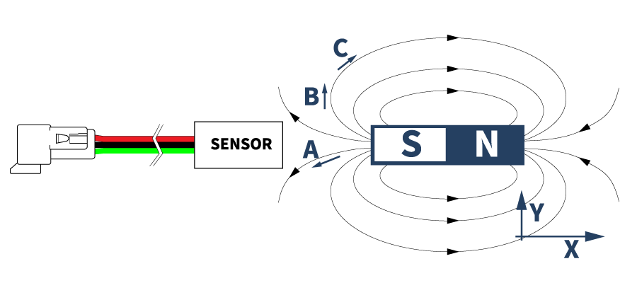
If a Hall sensor is pointed at the South pole as shown, the vector of the flux line in the -X direction, into the face is what the sensor element sees. If the sensor was at location A, most of the flux will be South Pole positive. If the sensor was at location B, the vector is completely in the Y direction, so the sensor element sees no field whatsoever.
If the sensor were at location C, the vector is mostly in the + X direction. So, this would represent the sensor element seeing a North Pole field.
So, if a magnet moves by a sensor as shown here, the sensor will see a field in this pattern: 0, then North pole, 0, South pole for a longer period, 0, North pole, then back to 0.
This will produce 3 pulses instead of one.
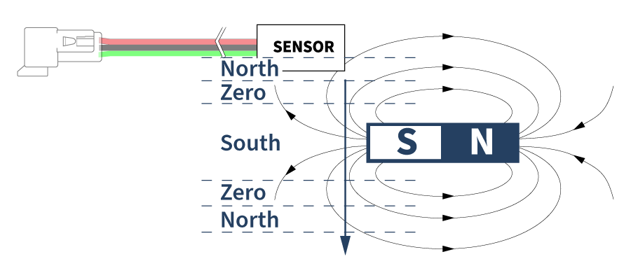
To resolve this issue, either use a normal South pole Hall Switch (HS, HS1), or increase the gap between the sensor and magnet far enough that the fringe North poles are not strong enough to trigger the sensor.
Application Notes
Sensor Selection Application Notes
Custom Speed Sensors & Direction Dependent Speed Switches
Custom Magnetic Sensor Design and Manufacturing
Guide to Replacing a Speed Sensor
Selecting the Appropriate Hall Effect Sensor and Target Magnet
Why do I need to provide the gear pitch when ordering a Speed and Direction Gear Tooth Sensor?
Target Selection Application Notes
Selection or Design of Sensor Targets
Selecting the Appropriate Hall Effect Sensor and Target Magnet
Sensor Behavior Application Notes
Chopper Stabilization and Gear Tooth Sensors
The Effect of Mounting A Ferrous Metal Sensor in a Steel Sleeve
Understanding Duty Cycle and Phase Angle in Quadrature Sensors
Why Either Pole Hall Switches May Produce 3 Pulses from a Single Magnet
Sensor Output Monitoring Application Notes
How to Hook Up an LED to a Magnetic Sensor
Understanding Duty Cycle and Phase Angle in Quadrature Sensors
Meters and Signal Conditioners
How To Hook Up a Digital Magnetic Sensor to a Relay
Custom Hall Sensor Application Notes
PCBA Manufacturing & Design – Printed Circuit Board Prototyping Services
Thief Hatch Latch Detection Systems
Talk to one of our Engineers. We have years of experience in designing custom Hall Effect sensors for new applications as well as OEM replacements. Contact out Engineering Department today to discuss your specific needs.
Click here to return the Hall Effect Application Notes page