
Understanding duty cycle and phase angle is essential for achieving accurate speed measurement, direction sensing, and reliable counting in quadrature sensor applications. This guide explains how duty cycle and phase angle affect quadrature sensor performance, how controllers interpret pulse signals, and why proper sensor and target selection are critical for precise motion detection. Whether you’re designing gear tooth sensing systems, rotary encoders, or direction-sensitive monitoring applications, learn the key principles that ensure accurate and dependable results. If you have any questions or would like to discuss your application, please contact our engineering department.
Overview
Traditional magnetic speed and direction sensors provide 2 outputs in one of the following forms:
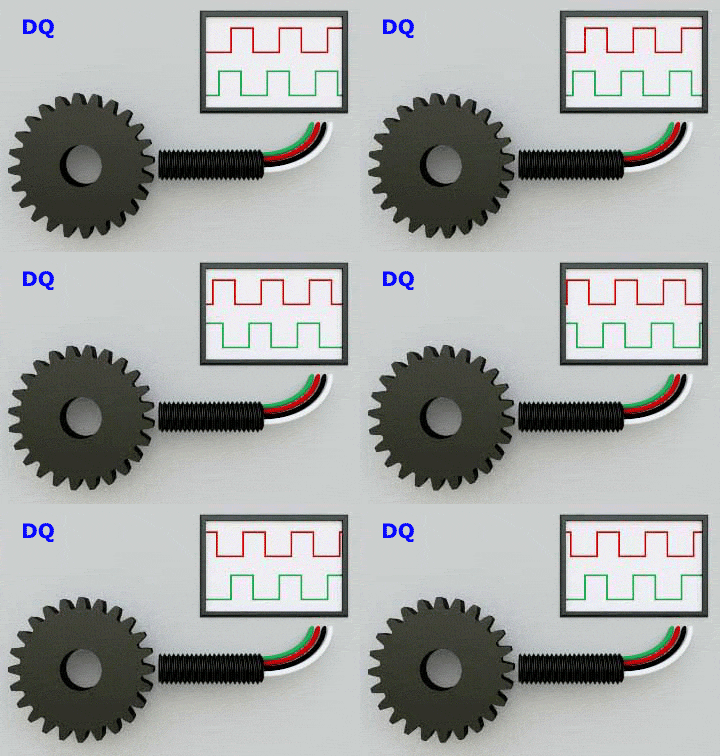
A) They provide 2 out of phase pulsing outputs detecting a gear, magnet(s), or other target(s)
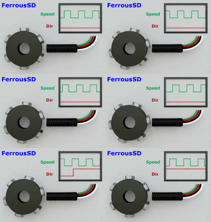
B) They provide one pulsing speed output and a high/low direction output.
With these applications typically a tachometer or other meter/controller monitors the outputs of the sensors to provide speed and direction feedback to an operator, or to directly control other electronic elements within the system.
Some applications may require:
- An output when movement is only in one direction; i.e. clockwise or forward.
- An output if a motor or drive shaft is moving in one direction and either above or below a specific speed.
- An output for movement in one direction, but only after a certain number of pulses.
- A directional output that can ignore a few broken or bent teeth.
For these types of applications Standex Detect has developed intelligent Directional Speed Switches and Pulsing Directional Speed Sensors that can be built to the specific requirements of an application. Pulse width modulated speed and direction sensors are currently in development and will be announced soon. Contact Standex Detect to determine if a PWM direction signal meets the requirements of your application.
Jump to: Overview | Types of Directional Speed Sensors Available | Directional Speed Switch | Directional Speed Sensor | Targets for Speed and Direction Sensors / Direction Dependent Speed Switches
Types of Directional Speed Sensors Available
Directional Speed Switch
A directional Speed Switch monitors the signals being provided by the sensing elements and resolves both the direction of movement, and whether the speed is above or below a defined rate. When the sensor detects motion in the defined direction above the defined speed the sensor output turns on until either the speed or the direction requirement is no longer being met.
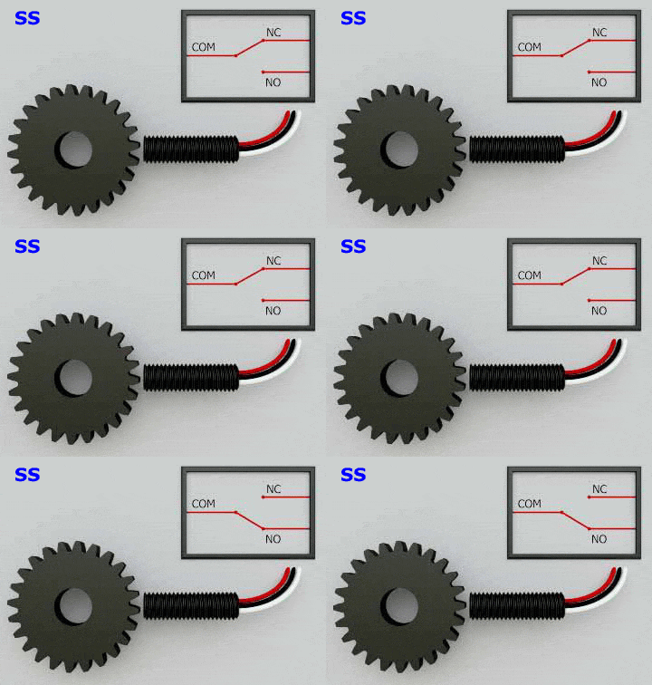
To provide a programmed directional speed switch for an application the sensors are built, programmed, and tested based on the following variables:
ON Speed
This is the speed (frequency in Hz) at which the output will turn on. This speed is typically calculated from RPM based on the number of pulses per revolution, but can also be calculated from rack gears and other linear motion targets
OFF Time
This is a time measurement that tells the output to turn off if the sensor has not seen a pulse.
Number of Consecutive ON Pulses: This is the number of pulses the sensor needs to detect above the ON Speed before switching the output.
ON Direction
This is direction of movement the target is moving relative to the sensor and determines how the sensor is oriented when installed to ensure the output only turns on when movement is in the desired direction.
Number of Consecutive Pulses to Confirm Direction Change
This is the number of pulses that need to be detected after direction changes before the sensor output registers the change in direction.
Application Example: A tractor has a power take off that should only be able to be turned on when the transmission output shaft is spinning in one direction at a speed greater than 100 RPM.
- ON Direction: The sensor is built so when mounted in front of a 60 tooth gear on the shaft the output will only turn on when the shaft is spinning clockwise.
- ON Speed: 100 RPM on a 60 tooth gear = 100 Hz
- OFF Time: AT 100 RPM the sensor pulses every 0.01 seconds. Setting the off time at .011 seconds will cause the output to turn off at 90.9 RPM. Having the OFF time to close to the operate speed can result in the output “chattering” on and off if the shaft is spinning close to the ON speed.
- Number of Consecutive ON Pulses: By setting this to 15, the sensor must see at least 15 pulses in a row (1/4 rotation) above the specified ON speed before the output will turn on
- Number of Consecutive Pulses to Confirm Direction Change: By setting this to 5 the sensor output will need to see 5 pulses in the same direction of rotation before indicating the output direction has changed.
Jump to: Overview | Types of Directional Speed Sensors Available | Directional Speed Switch | Directional Speed Sensor | Targets for Speed and Direction Sensors / Direction Dependent Speed Switches
Directional Speed Sensor
A directional Speed sensor monitors the signals being provided by the sensing element and resolves the direction of movement When the sensor detects motion in the defined direction it provides output pulses as the gear teeth, magnets, or other target pass the sensor face. If the target stops moving or moves in the opposite direction the output will not provide any pulses.
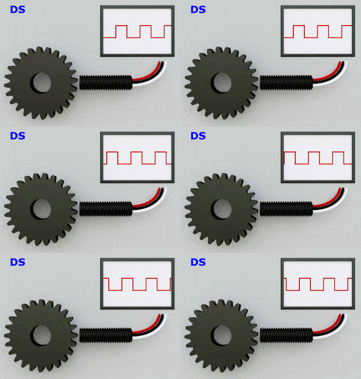
To provide a programmed directional speed sensor for an application the sensors are built, programmed, and tested based on the following variables:
ON Direction
This is direction of movement the target is moving relative to the sensor and determines how the sensor is oriented when installed to ensure the output only pulses when movement is in the desired direction.
Number of Consecutive Pulses to Confirm Direction Change
This is the number of pulses that need to be detected after direction changes before the sensor output registers the change in direction and either starts or stops.
Application Example: A conveyer system monitors belt speed and only opens a feeder to dump material onto the belt if it is moving. Periodically the conveyer direction is reversed for cleaning, but the feeder must remain closed during the cleaning process.
A standard single channel speed sensor can be replaced by a directional speed sensor so that when the conveyer runs backwards the feeder controller does not see any pulses from the sensor.
- ON Direction: The sensor is built so when mounted in front of a 60 tooth gear on the shaft the output will only turn on when the shaft is spinning clockwise.
- Number of Consecutive Pulses to Confirm Direction Change: By setting this to 5 the sensor output will need to see 5 pulses in the same direction of rotation before it either starts or stops providing output pulses.
Application Notes
Sensor Selection Application Notes
Custom Speed Sensors & Direction Dependent Speed Switches
Custom Magnetic Sensor Design and Manufacturing
Guide to Replacing a Speed Sensor
Selecting the Appropriate Hall Effect Sensor and Target Magnet
Why do I need to provide the gear pitch when ordering a Speed and Direction Gear Tooth Sensor?
Target Selection Application Notes
Selection or Design of Sensor Targets
Selecting the Appropriate Hall Effect Sensor and Target Magnet
Sensor Behavior Application Notes
Chopper Stabilization and Gear Tooth Sensors
The Effect of Mounting A Ferrous Metal Sensor in a Steel Sleeve
Understanding Duty Cycle and Phase Angle in Quadrature Sensors
Why Either Pole Hall Switches May Produce 3 Pulses from a Single Magnet
Sensor Output Monitoring Application Notes
How to Hook Up an LED to a Magnetic Sensor
Understanding Duty Cycle and Phase Angle in Quadrature Sensors
Meters and Signal Conditioners
How To Hook Up a Digital Magnetic Sensor to a Relay
Custom Hall Sensor Application Notes
PCBA Manufacturing & Design – Printed Circuit Board Prototyping Services
Thief Hatch Latch Detection Systems
Jump to: Overview | Types of Directional Speed Sensors Available | Directional Speed Switch | Directional Speed Sensor | Targets for Speed and Direction Sensors / Direction Dependent Speed Switches
Targets for Speed and Direction Sensors / Direction Dependent Speed Switches
Standex Detect programmed sensing solutions for resolving speed and direction are available for the detection of spur gears, rack gears, tone rings, and other ferrous sensor targets. They are also available for detecting permanent magnet targets as well. Additional Application Notes are also available with more information on magnetic sensor target selection and design as well as why speed and direction sensors are built and calibrated based on the details of the sensor target.
Need Custom Programming?
If you have an application where a programmed speed and direction sensor or direction-dependent speed switch feel free to contact us to discuss your options.
Click here to return the Hall Effect Application Notes page