Design safe, precise, and reliable high-voltage systems using reed relay technology across EV, energy storage, ATE, test and measurement equipment, and medical applications.
If there are particular areas you need help with, feel free to skip to any of the following sections:
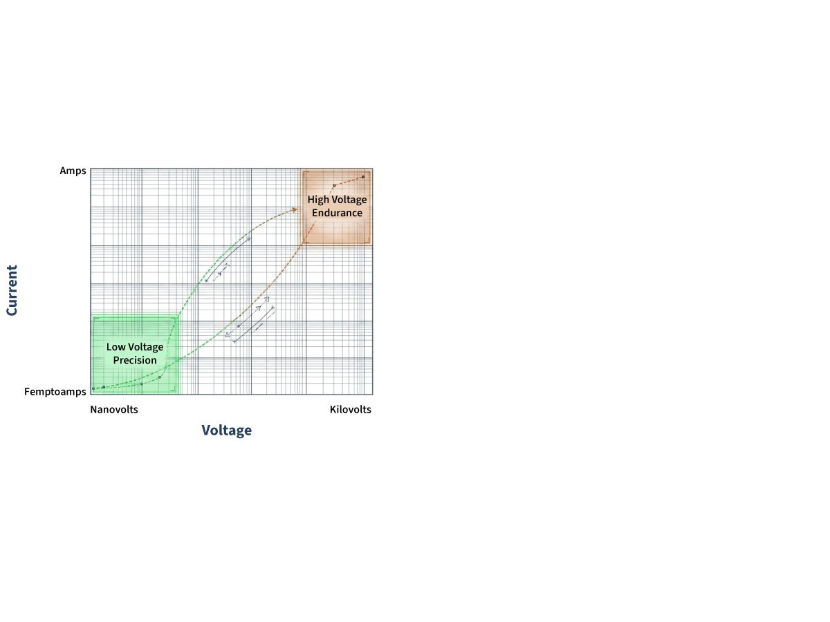
In Automated Test Equipment (ATE) and high-power electronics, a switch must handle extreme operational spectrums without signal degradation. Modern testing requires bridging nanovolt precision with kilovolt endurance.
Designing High-Voltage Systems with Precision Switching
Modern electrical systems demand switching solutions that can handle kilovolt-level stress while preserving microvolt-level measurement accuracy. Reed relays offer a unique combination of high isolation, low leakage, and long-term reliability, making them ideal for advanced test and power systems.
What You’ll Learn
- How to design high-voltage switching architectures
- Where reed relays fit across EV, ATE, and energy systems
- Key design rules for isolation, timing, and reliability
- Switching technology tradeoffs for Reed vs semiconductor vs EMRs
Jump to: High-Voltage System Design Patterns | Switching Design Rules | Engineering Resources | Reed Relay Design FAQ
Switching Voltage Vs Stand-Off Voltage
Switching voltage, stand-off voltage, and dielectric withstand voltage are different ratings. Relay selection should always consider the actual load type, voltage waveform, current, energy, switching frequency, and required safety margin.
Switching Voltage
What the relay can make or break under specified load conditions.
Breakdown or Stand-Off Voltage
Defines what the open contact can withstand without switching.
Dielectric Withstand Voltage
The isolation voltage capability between isolated parts of the relay, such as coil-to-contact.
Jump to: High-Voltage System Design Patterns | Switching Design Rules | Engineering Resources | Reed Relay Design FAQ
The Engineering Challenge of High-Voltage Switching
Bridging Precision and Power
In modern systems, engineers must reconcile two opposing demands:
- High-voltage endurance (kV-level switching)
- Ultra-low signal distortion (nano-/micro-volt accuracy)
Challenge
This creates a design challenge where switching devices must avoid:
- Leakage currents corrupting measurements
- Dielectric breakdown at high voltage
- Signal distortion from parasitics
Solution
Reed relays uniquely bridge this gap by supporting kilovolt-level signals when selected according to the required voltage, current, load type, switching power, duty cycle, and lifetime target. Reed relays can provide very low leakage and very high insulation resistance when correctly selected and integrated into a clean, well-designed circuit.
Actual leakage performance depends on the relay series, applied voltage, humidity, contamination, PCB layout, creepage and clearance, guarding strategy, and measurement method.
Relevant standards and design frameworks for Standex high-voltage relays:
- AEC-Q200
- IEC 61810-4
- IEC 60601-1
- IEC 62109-1/2
- IEC 60664-1
- ISO 6469-3
- IEC 60255-27
- UL Listed
- RohS, REACH
Jump to: High-Voltage System Design Patterns | Switching Design Rules | Engineering Resources | Reed Relay Design FAQ
Why Reed Relays Enable High-Voltage System Design
Core Engineering Advantages
- Hermetic Isolation
- Glass-sealed contacts eliminate contamination
- Enables stable performance in harsh and long-life environments
- Ultra-Low Leakage
- Insulation resistance >10¹³–10¹⁵ Ω
- Supports precision measurement systems
- Fast, Precise Switching
- <1 ms switching speeds
- Ideal for synchronized test systems
- No Wetting Current Requirement
- Enables switching in low-level signal applications
Jump to: High-Voltage System Design Patterns | Switching Design Rules | Engineering Resources | Reed Relay Design FAQ
Selecting the Right Switching Technology
Design Insight
High‑voltage switching decisions are architectural decisions. The technology you choose early affects isolation strategy, measurement accuracy, layout feasibility, and lifecycle risk. The guide below helps engineers align switching behavior with system priorities before detailed trade-off studies.
Quick Design Guide for High‑Voltage Systems
Reed Relays
Choose reed relays for mixed-signal switching (low-level + high voltage) and when isolation accuracy and long‑term signal stability matter more than raw switching speed.
Semiconductor
Choose semiconductor switching when speed dominates and higher leakage is acceptable.
EMRs
Choose EMRs when current is high and precision and speed are secondary.
Reed Relays Vs Other High-Voltage Switching Technologies
The below table is a quick high-voltage switching comparison of Reed vs solid-state and EMR relays.
| Feature | Reed Relays | Solid-State Semiconductor Relays | Electromechanical Relays (EMR) |
|---|---|---|---|
| Switching speed | Fast (<1 ms) | Extremely Fast (ns – µs) | Slower (5-15 ms) |
| Galvanic Isolation | High and Inherent, Low EMI (hermetically sealed) | Moderate (drivers required, can generate EMI) | Good (arcing risk) |
| Leakage current | Excellent (> 10 TOhm) | Moderate (temp dependent) | Good (can degrade with contact contamination) |
| Wetting current | None required | Required for conductivity | None required |
| Longevity | Millions + operations, load dependent | Very high (heat and voltage sensitive) | ~ 1 Million cycles (limited by mechanical wear) |
| Environmental | Mercury-free / Safe | Safe | Safe |
Engineers must balance speed, isolation, lifecycle, and signal integrity
Jump to: High-Voltage System Design Patterns | Switching Design Rules | Engineering Resources | Reed Relay Design FAQ
System Design Patterns Using Reed Relays
Engineers use reed relays in structured switching architectures to safely manage high voltage, current, and signal integrity across complex systems.
Pre-Charge Control in EV & Energy Storage
Design Problem:
Prevent inrush current when connecting high-voltage batteries to capacitive loads.
System Pattern:
- Close reed relay path through resistor
- Gradually charge capacitors (RC time constant)
- Close main contactor at ~90–95% voltage
- Open reed relay safely
Engineering Value:
- Prevents contact damage
- Enables controlled energy transfer
- Protects power electronics

High-Density Switching in ATE Systems
Design Problem:
Accurate measurement across thousands of test points
System Pattern:
- Relay matrices route signals between DUT and measurement units
- Must maintain signal integrity over millions of cycles
Why Reed Relays:
- Low thermal EMF
- Stable contact resistance
- Long life in high-cycle environments
High-Voltage Cable & Harness Testing
Design Problem:
Detect micro-shorts and partial failures
System Architecture:
- Matrix scanning applies high voltage across all nodes
- High current paths validate conductor integrity
Engineering Requirements:
- Up to 10 kV testing capability
- High isolation between channels
- Ability to carry pulse loads
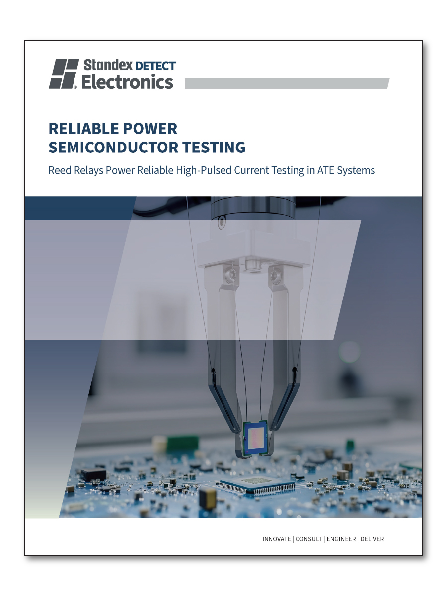
High-Pulsed Current Test Systems
Design Problem:
Generate clean high-current pulses without distortion
System Needs:
- Fast switching edges
- Low parasitic capacitance
- High current pulse handling
Reed Relay Benefit:
Supports clean waveform switching up to ~25A pulses
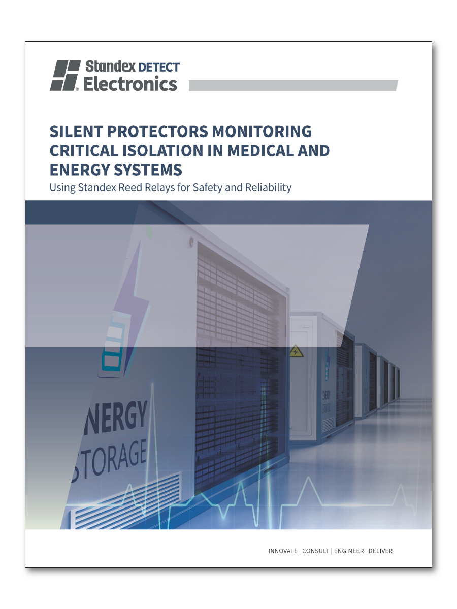
Safety Isolation in Medical and Energy Storage Systems
Design Problem:
Ensure patient safety in high-voltage environments
System Requirement:
- Absolute isolation between patient and equipment
Solution:
- Reed relays support isolation design in medical equipment with IEC 60601-1 compliance being verified at the equipment level.
- Reed relays are used in EV and ESS applications for measurement, monitoring, insulation testing, pre-charge control, signal switching, and test-system functions. They are not intended to replace high-current contactors in main power paths.
- Enable continuous isolation monitoring
Blog: Monitoring Insulation Measurement in Energy Storage Systems
Need Help Designing a High-Voltage Switching System?
Jump to: Engineering Resources | Reed Relay Design FAQ
Critical Design Rules for High-Voltage Relay Integration
To achieve safe and repeatable high‑voltage switching, engineers must apply proven design rules that address electrical spacing, isolation behavior, and transient conditions. These considerations help minimize leakage, prevent arc‑over, and ensure consistent long‑term operation.
Creepage & Clearance
- Design PCB spacing for high voltage
- Prevent surface tracking and arc-over
Design‑phase impact: Determines board size, layer stack‑up, and whether series relay architectures are required.
Switching Stabilization Timing
- Allow ~5 ms settling before applying load
- Prevent contact instability under high current
Design‑phase impact: Affects firmware timing, test sequencing, and measurement accuracy budgets.
Magnetic & Layout Considerations
- Use shielding to reduce coil-to-coil interference
- Optimize spacing and orientation for stable switching
- Control current paths to reduce EMI
- Minimize noise in precision measurement paths
Capacitive & Inductive Load Warning
- High-voltage reed relays must be selected with careful attention to load type. Capacitive loads can create high inrush current during turn-on, while inductive loads can generate voltage transients during turn-off.
- Protection components, pre-charge circuits, current limiting, snubbers, or derating may be required depending on the application.
- Do not select a relay only by maximum voltage and maximum current. Switching power, load energy, waveform, duty cycle, and lifetime requirements must also be considered.
- Define working voltage, transient voltage, and required safety margin before selecting the relay.
- Confirm whether the relay must switch voltage under load or only provide stand-off isolation.
- Design PCB creepage and clearance based on voltage, pollution degree, material group, coating, potting, and the relevant system standard.
- Use slots, barriers, guarding, or increased spacing where required.
- Keep high-voltage nodes clean and separated from low-voltage control circuits.
- Consider humidity, contamination, and surface leakage paths.
- Protect relay contacts from capacitive inrush and inductive transients.
- Validate the relay in the real circuit, not only from datasheet maximum ratings.
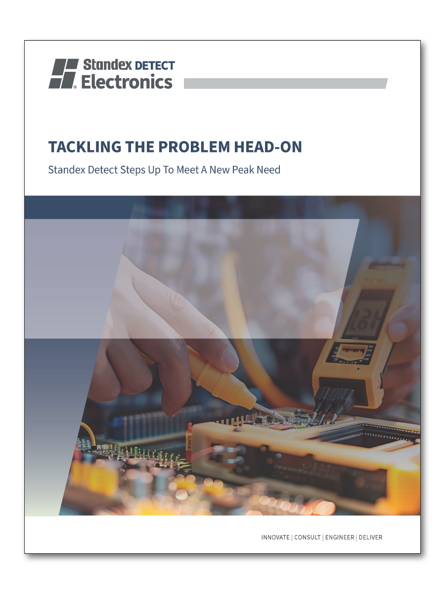
Engineering Constraint Example:
Solving High-Voltage Isolation in a Compact Design
Not all high-voltage design challenges can be solved with standard components. In this case, a constrained design environment required a creative relay solution to meet both voltage and space requirements, illustrating how tailored reed relay configurations can unlock new possibilities in advanced test and measurement systems.
Why This Matters Early in Design – This constraint was identified before schematic freeze, avoiding a full board redesign and months of schedule risk.
The Challenge
High-voltage testing required kilovolt-level isolation, but the PCB layout severely limited creepage and clearance. Conventional switching solutions could not meet both voltage and size requirements.
The Solution
A custom reed relay architecture used internally series-connected reed switches to increase voltage standoff while preserving a compact footprint and hermetic reliability.
The Result
The design achieved high-voltage isolation compliance, fit within existing board constraints, and eliminated the need for system redesign, delivering a robust, scalable solution.
The Engineering Approach:
Rather than redesigning the system or increasing board space, engineers implemented a custom reed relay configuration using two reed switches connected internally in series. This architecture increased effective creepage distance and voltage standoff within a compact package.
- Increased dielectric strength without expanding PCB footprint
- Maintained hermetically sealed contact reliability
- Preserved switching stability and signal integrity
Key Takeaway for Engineers:
High-voltage system performance depends as much on architecture as on component ratings. Reed relay configurations can be adapted to meet extreme isolation requirements, even in space-constrained designs.
Jump to: Reed Relay Design FAQ
Engineering Resource Library
Access a comprehensive collection of application notes, case studies, and brochures focused on high-voltage switching design. Explore proven approaches for EV systems, automated test equipment (ATE), energy storage, and cable testing, along with practical insights to help you optimize performance, isolation, and reliability.
Dive into our expertly curated Reed Technology Academy for comprehensive training and technical guides. Whether you’re an engineer, designer, or curious learner, gain practical insights into reed switch design, functionality, and applications.

FAQ: Reed Relays for High-Voltage
These frequently asked questions address common engineering considerations when designing high‑voltage switching systems with reed relays, including applications, performance tradeoffs, isolation requirements, and system‑level design best practices.
Click a question below to explore detailed answers.
What voltage levels can reed relays handle?
High‑voltage reed relays can handle voltage levels ranging from several hundred volts to multiple kilovolts, depending on design and configuration. Achievable voltage performance is influenced by internal spacing, series configurations, and system‑level creepage and clearance design.
Voltage handling varies across different product series based on their intended application:
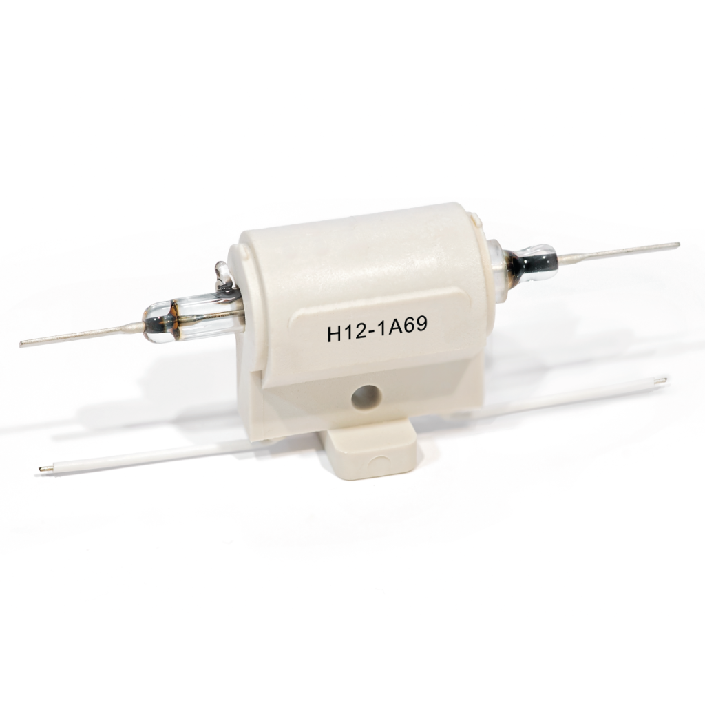
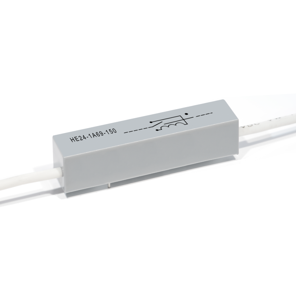
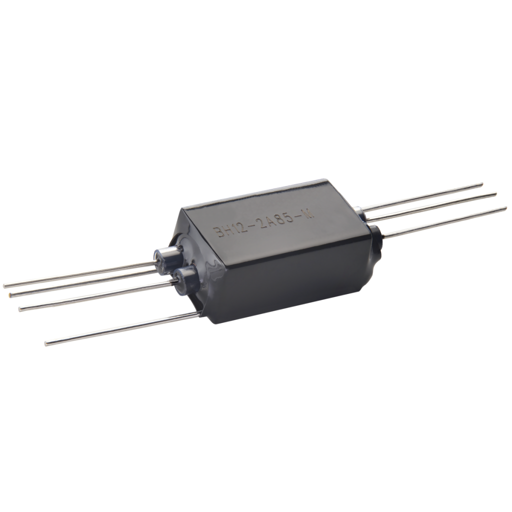
- Extreme High-Voltage (H, HE, and HM Series): Engineered for maximum isolation, these series switch up to 10 kVDC and can provide isolation up to 20 kVDC. The HE/HM series can also hold off 15,000 volts between the switch and the coil.
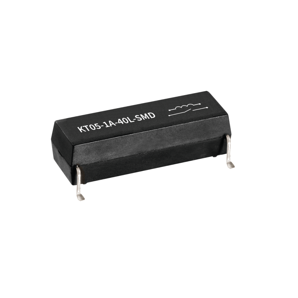
- Compact High-Voltage (KT and KTP Series): These are often used in EV pre-charge circuits and renewable energy systems. The KT series switches up to 1.5 kVDC with a 6 kV breakdown and 7 kVDC isolation. The KTP series is an enhanced version capable of switching up to 2.5 kVDC.
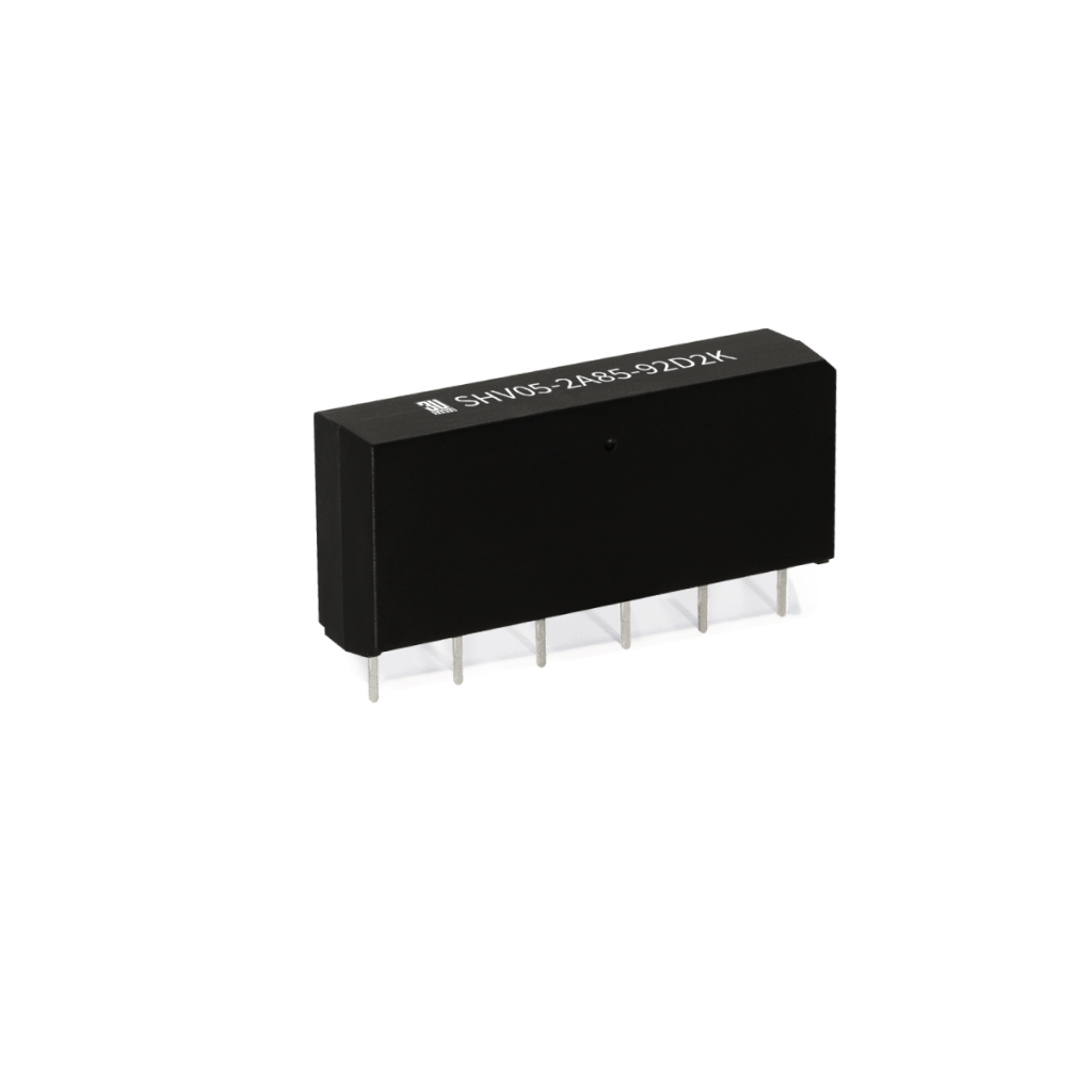
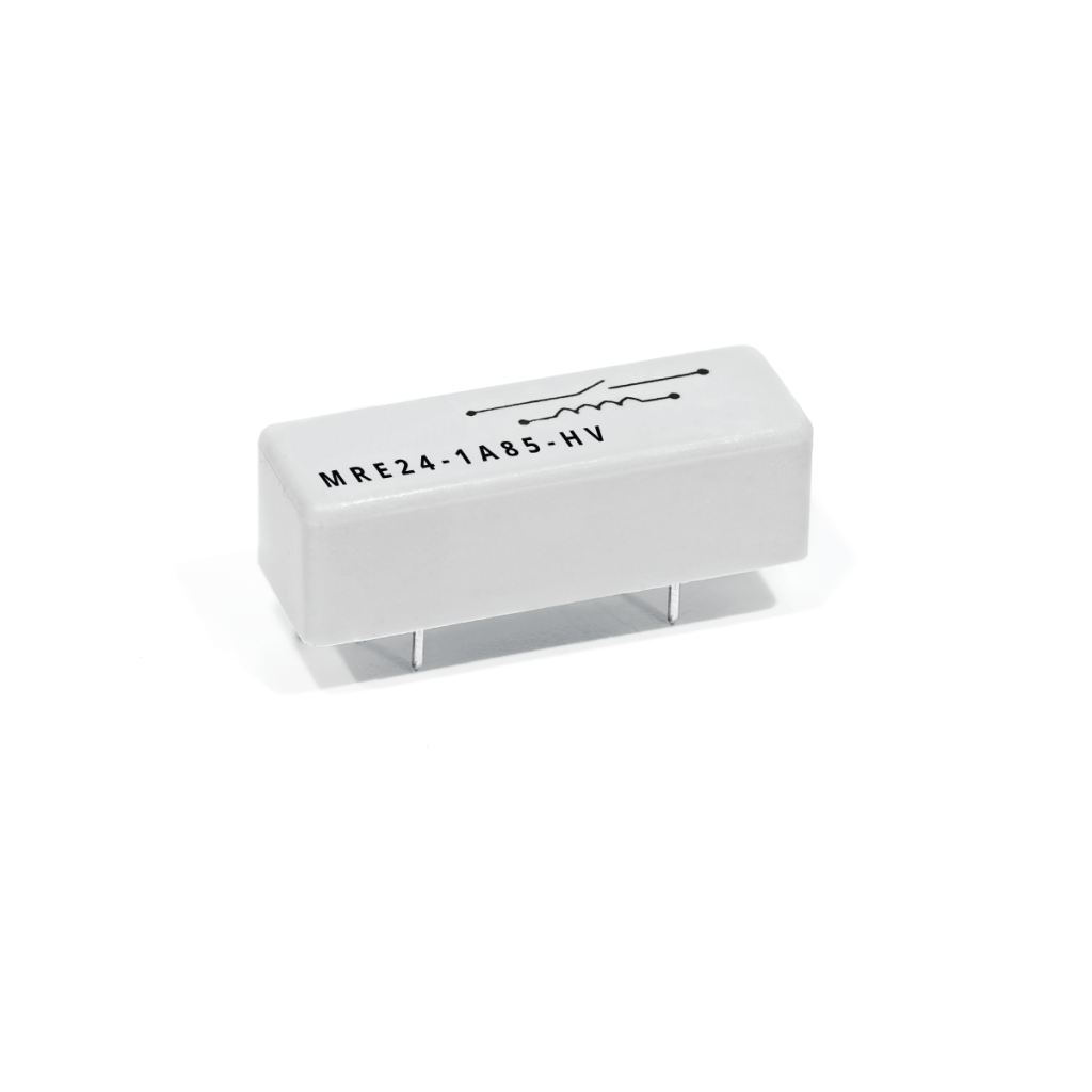
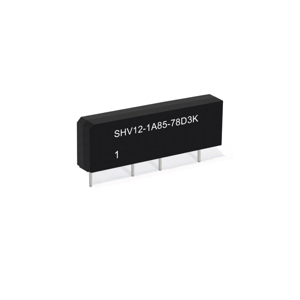
- Test and Measurement Platforms (SHV and MRE Series): Designed for high-current ATE requirements, these relays switch up to 1.5 kVDC and offer a dielectric strength of 7,000 V.
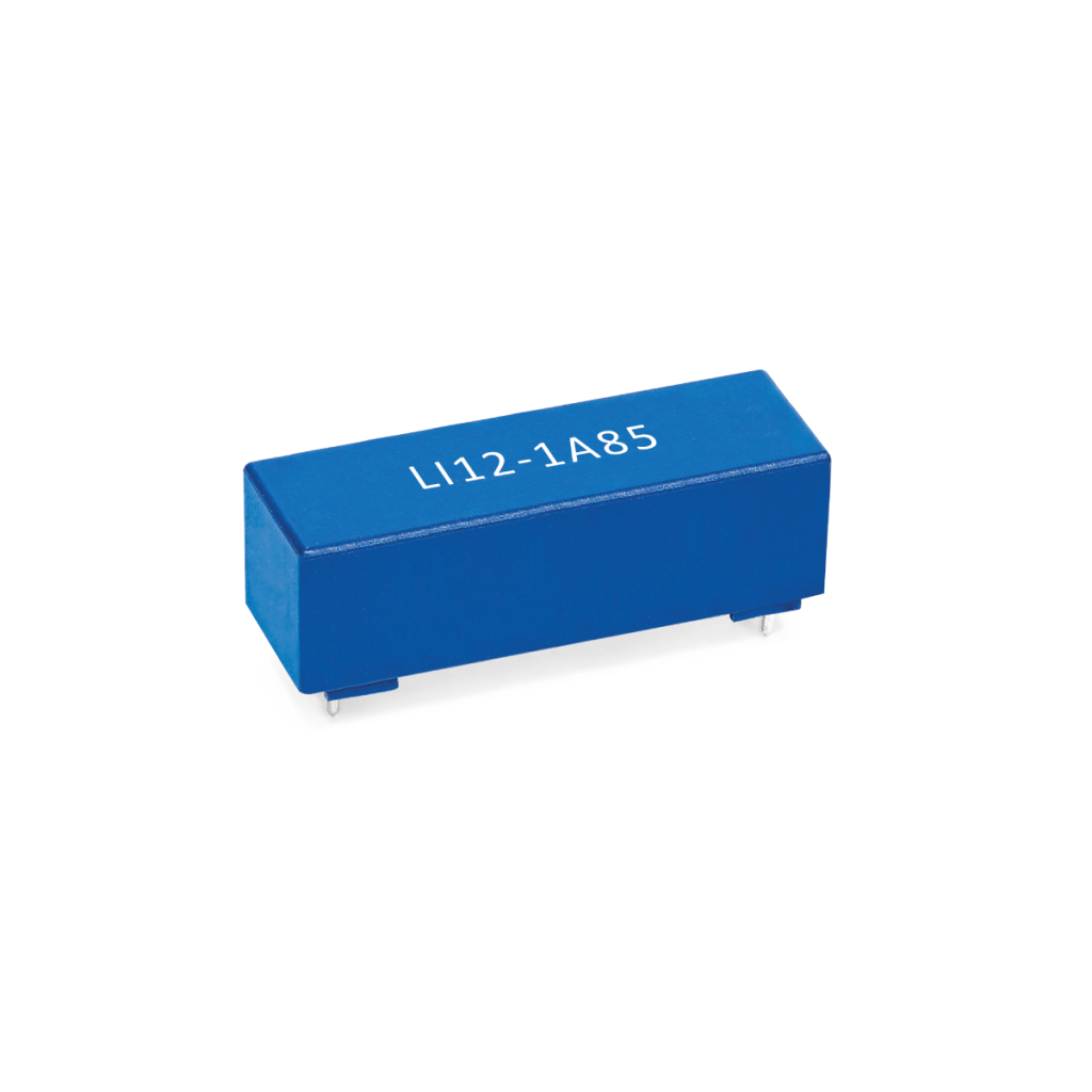
- General Purpose High-Voltage (LI, BH, BE, and MHV Series): These compact relays typically support switching voltages up to 1,000 VDC (1 kVDC). Breakdown voltages for these series range from 3 kVDC (BH series) up to 4 kVDC (LI, SHV, and BE series).
For applications with even higher requirements, multiple reed switches can be internally connected in series within a single relay package (such as the MRE Series) to achieve greater voltage performance in a compact footprint.
Can I use the maximum voltage and maximum current ratings at the same time?
No, not automatically. Maximum voltage, maximum current, and maximum power ratings are defined under specific test conditions and load types. When operating close to the relay’s limits, selection should also consider switching power, load energy, inrush current, waveform, duty cycle, and required lifetime to help ensure reliable performance.
For high-voltage applications, contact Standex engineering support to confirm the correct relay selection.
What are high-voltage reed relays used for?
High‑voltage reed relays are used in applications requiring precise switching and high electrical isolation, such as EV battery systems, automated test equipment (ATE), cable testing, and medical devices.
They are commonly applied where kilovolt‑level voltages must be switched while maintaining low leakage current and accurate signal integrity across multiple test points or system nodes.
Why are reed relays used in high‑voltage switching systems?
Reed relays are used in high‑voltage switching systems because they provide high isolation, ultra‑low leakage current, and stable performance over millions of switching cycles.
Their hermetically sealed contacts protect against contamination and oxidation, making them well‑suited for environments where reliability and measurement accuracy are critical.
Are reed relays better than solid‑state relays for high voltage?
Reed relays are often better than solid‑state relays for high‑voltage applications that require low leakage current and precise signal integrity.
While solid‑state relays offer faster switching, reed relays provide superior isolation and lower leakage, making them ideal for precision measurement and test systems.
How do reed relays improve accuracy in test and measurement systems?
Reed relays improve test system accuracy by minimizing leakage current, thermal EMF, and parasitic effects that can distort low‑level signals.
This allows engineers to maintain consistent measurement integrity in high‑density relay matrices, even when switching between low‑level signals and high‑voltage test conditions.
How are reed relays used in EV pre‑charge circuits?
In EV pre‑charge circuits, reed relays are used to safely control inrush current when connecting a high‑voltage battery to a capacitive load.
The relay closes first to route current through a limiting resistor, allowing system capacitors to charge gradually before the main contactor closes, reducing stress on power electronics and contactors.
What design considerations are important for high‑voltage relay integration?
Key design considerations for high‑voltage relay integration include creepage and clearance distances, insulation coordination, switching stabilization timing, and PCB layout.
These factors help prevent arc‑over, leakage, and long‑term reliability issues, ensuring the switching system performs safely and consistently under high‑voltage conditions.
When should engineers choose reed relays over other switching technologies?
Engineers should choose reed relays when applications require high isolation, low leakage current, precise switching, and long operational life.
They are especially effective in mixed‑signal environments where both low‑level measurements and high‑voltage switching must coexist, while other technologies may be better suited for ultra‑fast (semiconductors) or purely high‑current applications (EMRs).
Can reed relays handle both high voltage and high current?
Yes, certain reed relay designs (SHV and MRE Series) can handle both high voltage and moderate to high current, including pulsed current applications.
However, performance depends on relay construction, duty cycle, and thermal considerations, making system‑level design and proper rating selection essential.
How do reed relays support insulation monitoring in energy storage systems?
Reed relays support insulation monitoring by providing high isolation between measurement points, enabling accurate detection of leakage and insulation faults.
Their low leakage characteristics help ensure insulation resistance measurements remain reliable, supporting safety and compliance in energy storage and renewable systems.
From System Design to Component Selection
Once system requirements are defined such as voltage, current, isolation, and switching speed, the next step is selecting the appropriate relay architecture.
High-Voltage Reed Relay Selection Checklist
Before selecting a high-voltage reed relay, define the following:
| Required switching voltage | |
| Required stand-off voltage | |
| AC, DC, or pulsed waveform | |
| Load type: resistive, capacitive, inductive, or mixed | |
| Switching current and carry current | |
| Switching power and load energy | |
| Hot switching or cold switching | |
| Required insulation resistance or leakage current |
| Contact form | |
| Coil voltage | |
| PCB, cable, or panel mounting | |
| Creepage and clearance requirement | |
| Operating temperature and humidity | |
| Expected lifetime and switching frequency | |
| Applicable system-level requirements |
Check out our newest released reed relay series!
Engineered for maximum isolation, these series switch up to 10 kVDC and can provide isolation up to 20 kVDC. The HE/HM series can also hold off 15,000 volts between the switch and the coil.

Designed for high-current ATE requirements, these relays switch up to 1.5 kVDC and offer a dielectric strength of 7,000 V.
These are often used in EV pre-charge circuits and renewable energy systems. The KT series switches up to 1.5 kVDC with a 6 kV breakdown and 7 kVDC isolation. The KTP series is an enhanced version capable of switching up to 2.5 kVDC.
These compact relays typically support switching voltages up to 1,000 VDC (1 kVDC). Breakdown voltages for these series range from 3 kVDC (BH series) up to 4 kVDC (LI, SHV, and BE series).


Partnering for Precision
For When it Matters – The Right Design, at the Right Time, at the Optimal Cost.
Designing with high-voltage reed relays is not just about selecting components, it’s about ensuring long-term system performance, reliability, and safety under real-world conditions. From managing insulation coordination and creepage distances to minimizing leakage current in isolation monitoring applications and maintaining signal integrity in high-voltage test systems, every design decision impacts your platform’s success.
That’s why leading engineers partner with Standex Detect, not simply as a component supplier, but as a fully integrated engineering and manufacturing partner for high-voltage switching solutions.
End-to-End Design
With end-to-end control from reed switch fabrication to finished HV relay assembly, Standex Detect designs, manufactures, tests, and qualifies solutions entirely in-house. This vertical integration ensures consistent quality, stable supply, and faster development cycles, critical advantages for applications requiring high-voltage isolation, low leakage switching, and long-term reliability.
Custom Engineered
Our approach goes beyond standard products. While many designs begin with a catalog relay, more than 35,000 customer programs have evolved into custom-engineered reed relay solutions, tailored to exact electrical, mechanical, and environmental requirements. Whether optimizing creepage and clearance for kV-level isolation, refining shielding for low noise signal paths, or tuning coil and contact characteristics for lifetime performance, every parameter is engineered to fit the application, not the other way around.
Global Manufacturing
Equally important is global scale. With engineering and manufacturing operations across North America, Europe, and Asia, Standex Detect provides the flexibility and supply chain resilience required for high-reliability HV relay programs, from prototype through full production.
Application Leadership
This capability is grounded in deep technical leadership. As the world’s largest manufacturer of reed switches (>700 million annually), Standex Detect combines materials science expertise with proprietary life-cycle testing and application-specific validation to ensure consistent performance in demanding environments such as EV battery and energy systems, semiconductor ATE, medical high-voltage equipment, and industrial insulation monitoring systems.
Co-Engineering Partnership
Most importantly, collaboration begins early. Standex Detect works directly with your engineering team, from concept and simulation through validation and production, to optimize high-voltage switching performance, reduce design risk, and accelerate time to market in complex systems requiring precision signal routing, isolation, and measurement accuracy.
The result is more than a relay, it’s a precisely engineered high-voltage switching solution designed for your application’s electrical, environmental, and lifecycle demands.
When precision, reliability, and lifecycle performance matter most, Standex Detect delivers engineered high-voltage relay solutions, not just components.
Engineer Your Next
High-Voltage Design
When performance, isolation, and long-term reliability matter, the right partner makes the difference.
Standex Detect works alongside your team to design, validate, and deliver switching solutions optimized for your exact application, not forced into standard constraints.
What You Gain:
- Custom-engineered relay solutions tailored to your requirements
- Support from concept through validation and production
- Proven performance in high-voltage, high-reliability systems
- Global manufacturing with supply chain stability